TOP Contributors

  1. MIKROE (2654 codes)
  2. Alcides Ramos (352 codes)
  3. Shawon Shahryiar (307 codes)
  4. jm_palomino (112 codes)
  5. Chisanga Mumba (90 codes)
  6. S P (73 codes)
  7. dany (71 codes)
  8. MikroBUS.NET Team (35 codes)
  9. NART SCHINACKOW (34 codes)
  10. Armstrong Subero (27 codes)

Most Downloaded

  1. Timer Calculator (136746 times)
  2. FAT32 Library (69953 times)
  3. Network Ethernet Library (55942 times)
  4. USB Device Library (46267 times)
  5. Network WiFi Library (41887 times)
  6. FT800 Library (41174 times)
  7. GSM click (28986 times)
  8. PID Library (26414 times)
  9. mikroSDK (26363 times)
  10. microSD click (25377 times)
Libstock prefers package manager

Package Manager

We strongly encourage users to use Package manager for sharing their code on Libstock website, because it boosts your efficiency and leaves the end user with no room for error. [more info]

< Back
mikroSDK Library

MCP2517FD click

Rating:

6

Author: MIKROE

Last Updated: 2022-03-08

Package Version: 1.0.0.1

mikroSDK Library: 1.0.0.0

Category: CAN

Downloaded: 9432 times

Not followed.

License: MIT license  

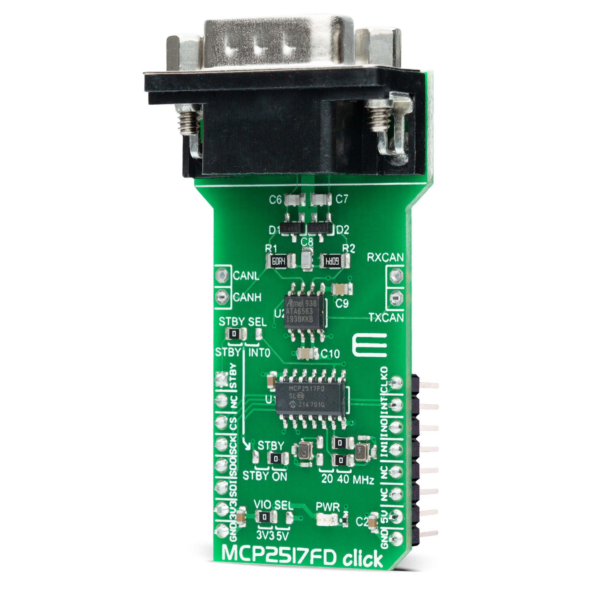
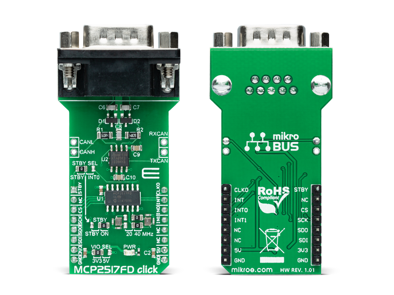
MCP2517FD Click is a compact add-on board representing a complete CAN solution used as a control node in a CAN network. This board features the MCP2517FD and ATA6563, an external CAN FD controller with an SPI interface, and a high-speed CAN transceiver from Microchip. The ATA6563, a low-level physical layer IC (PHY), provides a physical connection with the CAN bus itself, while the CAN controller MCP2517FD represents an interface between the MCU and the PHY. It features three operating modes with dedicated fail-safe features, remote wake-up via CAN, and ideally passive behavior when powered off on the CAN bus. This Click board™ is suitable for developing a wide range of automotive diagnostic applications, even on MCUs that don’t support CAN interface.

No Abuse Reported

Do you want to subscribe in order to receive notifications regarding "MCP2517FD click" changes.

Do you want to unsubscribe in order to stop receiving notifications regarding "MCP2517FD click" changes.

Do you want to report abuse regarding "MCP2517FD click".

  • mikroSDK Library 2.0.0.0
  • Comments (0)
DOWNLOAD LINK RELATED COMPILER CONTAINS
mikroBasic PRO for ARM
  • lib
  • src
  • exa
  • hlp
  • hex
  • sch
  • pcb
  • doc
mikroBasic PRO for AVR
  • lib
  • src
  • exa
  • hlp
  • hex
  • sch
  • pcb
  • doc
mikroBasic PRO for dsPIC30/33 & PIC24
  • lib
  • src
  • exa
  • hlp
  • hex
  • sch
  • pcb
  • doc
mikroBasic PRO for FT90x
  • lib
  • src
  • exa
  • hlp
  • hex
  • sch
  • pcb
  • doc
mikroBasic PRO for PIC
  • lib
  • src
  • exa
  • hlp
  • hex
  • sch
  • pcb
  • doc
mikroBasic PRO for PIC32
  • lib
  • src
  • exa
  • hlp
  • hex
  • sch
  • pcb
  • doc
mikroC PRO for ARM
  • lib
  • src
  • exa
  • hlp
  • hex
  • sch
  • pcb
  • doc
mikroC PRO for AVR
  • lib
  • src
  • exa
  • hlp
  • hex
  • sch
  • pcb
  • doc
mikroC PRO for dsPIC30/33 & PIC24
  • lib
  • src
  • exa
  • hlp
  • hex
  • sch
  • pcb
  • doc
mikroC PRO for FT90x
  • lib
  • src
  • exa
  • hlp
  • hex
  • sch
  • pcb
  • doc
mikroC PRO for PIC
  • lib
  • src
  • exa
  • hlp
  • hex
  • sch
  • pcb
  • doc
mikroC PRO for PIC32
  • lib
  • src
  • exa
  • hlp
  • hex
  • sch
  • pcb
  • doc
mikroPascal PRO for ARM
  • lib
  • src
  • exa
  • hlp
  • hex
  • sch
  • pcb
  • doc
mikroPascal PRO for AVR
  • lib
  • src
  • exa
  • hlp
  • hex
  • sch
  • pcb
  • doc
mikroPascal PRO for dsPIC30/33 & PIC24
  • lib
  • src
  • exa
  • hlp
  • hex
  • sch
  • pcb
  • doc
mikroPascal PRO for FT90x
  • lib
  • src
  • exa
  • hlp
  • hex
  • sch
  • pcb
  • doc
mikroPascal PRO for PIC
  • lib
  • src
  • exa
  • hlp
  • hex
  • sch
  • pcb
  • doc
mikroPascal PRO for PIC32
  • lib
  • src
  • exa
  • hlp
  • hex
  • sch
  • pcb
  • doc

mikroSDK Library Blog

MCP2517FD click

MCP2517FD click

Native view of the MCP2517FD click board.

View full image
MCP2517FD Click

MCP2517FD Click

Front and back view of the MCP2517FD click board.

View full image

Library Description

Library offers a choice to exchange messages with the other device by using CAN communication. Library also offers a choice to access a control, status and RAM registers of the device. For more details check documentation.

Key functions:

  • void MCP2517FD_transmitMessage( uint8_t numDataBytes, uint8_t *transmitFlag, uint8_t *dataIn ) - Transmits the desired message and checks is message successfully sent.
  • void MCP2517FD_receiveMessage( uint8_t *receiveFlag, uint8_t *dataOut ) - Receives the message and checks is message successfully received.
  • int8_t MCP2517FD_Configure(T_MCP2517FD_id index, T_MCP2517FD_cfg* config) - CAN Control register configuration.
  • int8_t MCP2517FD_ConfigureObjectReset(T_MCP2517FD_cfg* config) - Reset Configure object to reset values.

Examples description

The application is composed of three sections :

  • System Initialization - Initializes peripherals and pins.
  • Application Initialization - Initializes SPI interface and performs the device configuration to work properly.
  • Application Task - (code snippet) - Always checks is a new message in FIFO ready for receiving and when is message ready, receives a message from the other device. Also in this example we can send the desired message via CAN communication to the other device. We can choose a message to be sent by sending the determined command to the UART. In this example the command can be number from 1 to 7.
void applicationTask()
{
    if (UART_Rdy_Ptr())
    {
        rxDat = UART_Rd_Ptr();
        chPtr = &txd[0];

        switch (rxDat)
        {
            case '1' :
            {
                _strcpy( chPtr, &txtMessage1[0] );
                MCP2517FD_transmitMessage( 5, &checkFlag, &txd[0] );
                if (checkFlag == 1)
                {
                    mikrobus_logWrite( "Message Sent", _LOG_LINE );
                }
            break;
            }
            case '2' :
            {
                _strcpy( chPtr, &txtMessage2[0] );
                MCP2517FD_transmitMessage( 7, &checkFlag, &txd[0] );
                if (checkFlag == 1)
                {
                    mikrobus_logWrite( "Message Sent", _LOG_LINE );
                }
            break;
            }
            case '3' :
            {
                _strcpy( chPtr, &txtMessage3[0] );
                MCP2517FD_transmitMessage( 2, &checkFlag, &txd[0] );
                if (checkFlag == 1)
                {
                    mikrobus_logWrite( "Message Sent", _LOG_LINE );
                }
            break;
            }
            case '4' :
            {
                _strcpy( chPtr, &txtMessage4[0] );
                MCP2517FD_transmitMessage( 4, &checkFlag, &txd[0] );
                if (checkFlag == 1)
                {
                    mikrobus_logWrite( "Message Sent", _LOG_LINE );
                }
            break;
            }
            case '5' :
            {
                _strcpy( chPtr, &txtMessage5[0] );
                MCP2517FD_transmitMessage( 3, &checkFlag, &txd[0] );
                if (checkFlag == 1)
                {
                    mikrobus_logWrite( "Message Sent", _LOG_LINE );
                }
            break;
            }
            case '6' :
            {
                _strcpy( chPtr, &txtMessage6[0] );
                MCP2517FD_transmitMessage( 3, &checkFlag, &txd[0] );
                if (checkFlag == 1)
                {
                    mikrobus_logWrite( "Message Sent", _LOG_LINE );
                }
            break;
            }
            case '7' :
            {
                _strcpy( chPtr, &txtMessage7[0] );
                MCP2517FD_transmitMessage( 7, &checkFlag, &txd[0] );
                if (checkFlag == 1)
                {
                    mikrobus_logWrite( "Message Sent", _LOG_LINE );
                }
            break;
            }
            default :
            {
            break;
            }
        }
    }

    MCP2517FD_receiveMessage( &checkFlag, &rxd[0] );
    if (checkFlag == 1)
    {
        chPtr = &rxd[0];
        mikrobus_logWrite( "Received Message : ", _LOG_TEXT );
        mikrobus_logWrite( chPtr, _LOG_LINE );
    }
}

Other mikroE Libraries used in the example:

  • SPI
  • UART

Additional notes and informations

Depending on the development board you are using, you may need USB UART clickUSB UART 2 click or RS232 click to connect to your PC, for development systems with no UART to USB interface available on the board. The terminal available in all MikroElektronika compilers, or any other terminal application of your choice, can be used to read the message.

ALSO FROM THIS AUTHOR

SpeakUp 3 click

0

SpeakUP 3 Click is a compact add-on board providing an offline speech recognition solution. This board features the VC-02, a low-cost pure offline speech recognition module developed by Ai-Thinker Technology. The VC-02 module uses an integrated voice chip US516P6 based on a 32-bit RSIC architecture core, a DSP instruction set for signal processing and speech recognition, an FPU arithmetic unit, and an FFT accelerator. The VC-02 supports offline identification of 150 local instructions, RTOS lightweight system, firmware update feature, as well as the selection of the communication method with the module.

[Learn More]

SPIRIT click

6

SPIRIT click carries the SP1ML 868MHz ultra low-power RF module. The click is designed to run on a 3.3V or 5V power supply. It communicates with the target MCU over UART interface, with additional functionality provided by the following pins on the mikroBUS line: PWM, RST, CS.

[Learn More]

Light Temp click

5

Light Temp Click is a dual-channel LED driver, designed to be used in tunable Smart Connected Lighting (SCL) applications. It is based on the AL1782, a dual-channel PWM dimmable linear LED driver.

[Learn More]