20%

We strongly encourage users to use Package manager for sharing their code on Libstock website, because it boosts your efficiency and leaves the end user with no room for error. [more info]

Rating:
Author: Dick Berry
Last Updated: 2016-02-18
Package Version: 4.0.0.0
Category: Measurement
Downloaded: 1346 times
Followed by: 2 users
License: MIT license
This is a Monitor system for Travel Trailers, Pop Up's and other RV's. I have made provisions for two displays, one inside and one outside. A single button for each display steps through the modes. Modes include
Battery Voltage:
Fresh Water Level:
Outside Temp:
Inside Temp:
Cycle The Data Displays:
Off:
Thanks For Looking
Dick
Do you want to subscribe in order to receive notifications regarding "RV Monitor System Two Displays, Battery Voltage, Fresh Water Level, Outside Temp, Inside Temp, With Cycleing Mode" changes.
Do you want to unsubscribe in order to stop receiving notifications regarding "RV Monitor System Two Displays, Battery Voltage, Fresh Water Level, Outside Temp, Inside Temp, With Cycleing Mode" changes.
Do you want to report abuse regarding "RV Monitor System Two Displays, Battery Voltage, Fresh Water Level, Outside Temp, Inside Temp, With Cycleing Mode".
| DOWNLOAD LINK | RELATED COMPILER | CONTAINS |
|---|---|---|
| 1375505607_rv_monitor_syste_mikrobasic_pic.zip [2.43MB] | mikroBasic PRO for PIC |
|
This is a Monitor system for Travel Trailers, Pop Up's and other RV's. I have made provisions for two displays, one inside and one outside. A single button for each display steps through the modes. Modes include
Battery Voltage:
Fresh Water Level:
Outside Temp:
Inside Temp:
Cycle The Data Displays:
Off:
Each Display is independent of the other. That is they can be in any mode regardless of the state of the other display.
I haven't bread boarded this yet but it's working on my EasyPIC V7. I'm still waiting for some hardware to complete the first target board. So there will no doubt be a Version 2.0, but I did want to hear any comments you guys may have as early as possible.
Included are:
Assembly Docs for the OEM hardware bits I bought
All the Source Code
And I did find some handy GIF files for the schematic drawing so I left them in the package.
I'll update this Blog with Pictures when I have enough to be meaningful.
Thanks For Looking
Dick
Update 6/24/2013
It's been a busy couple weeks! I ran into Ram management problems and had to reorg the code to keep all the ram usage in the lower bank, but so far I've managed to avoid manual bank switching.
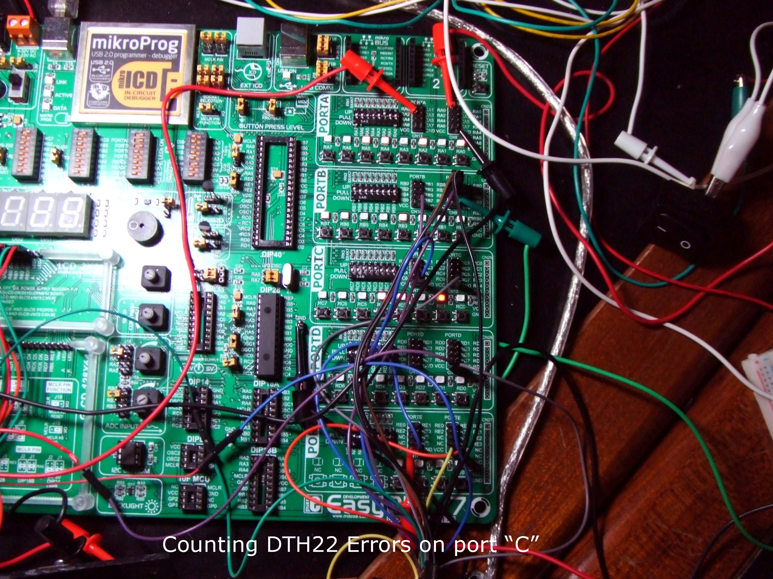
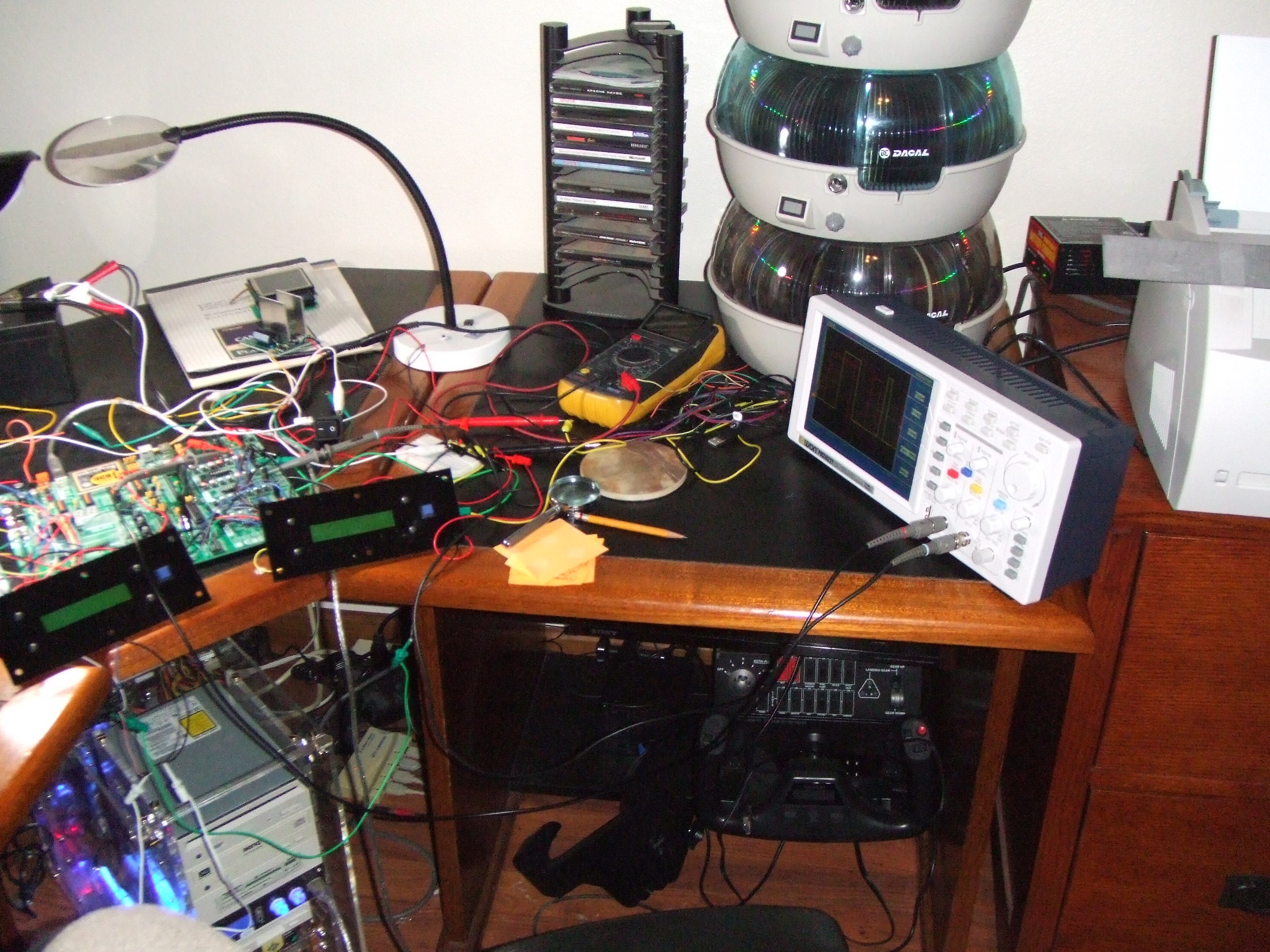
I changed the Temp Sensors to the DHT22 modules. Mostly because they come in a package that is easy to mount outside. Also getting Relative Humidity isn't a bad thing. The timing on these things is pretty critical especially if your running an interrupt, but it's doable. A good "O" Scope is almost required for the adjustments. I have one coming, hopefully today but so far I have been able to get it working without. It really is required to wait two seconds between sampling, but when your talking about Temperature and Humidity that's not an issue.
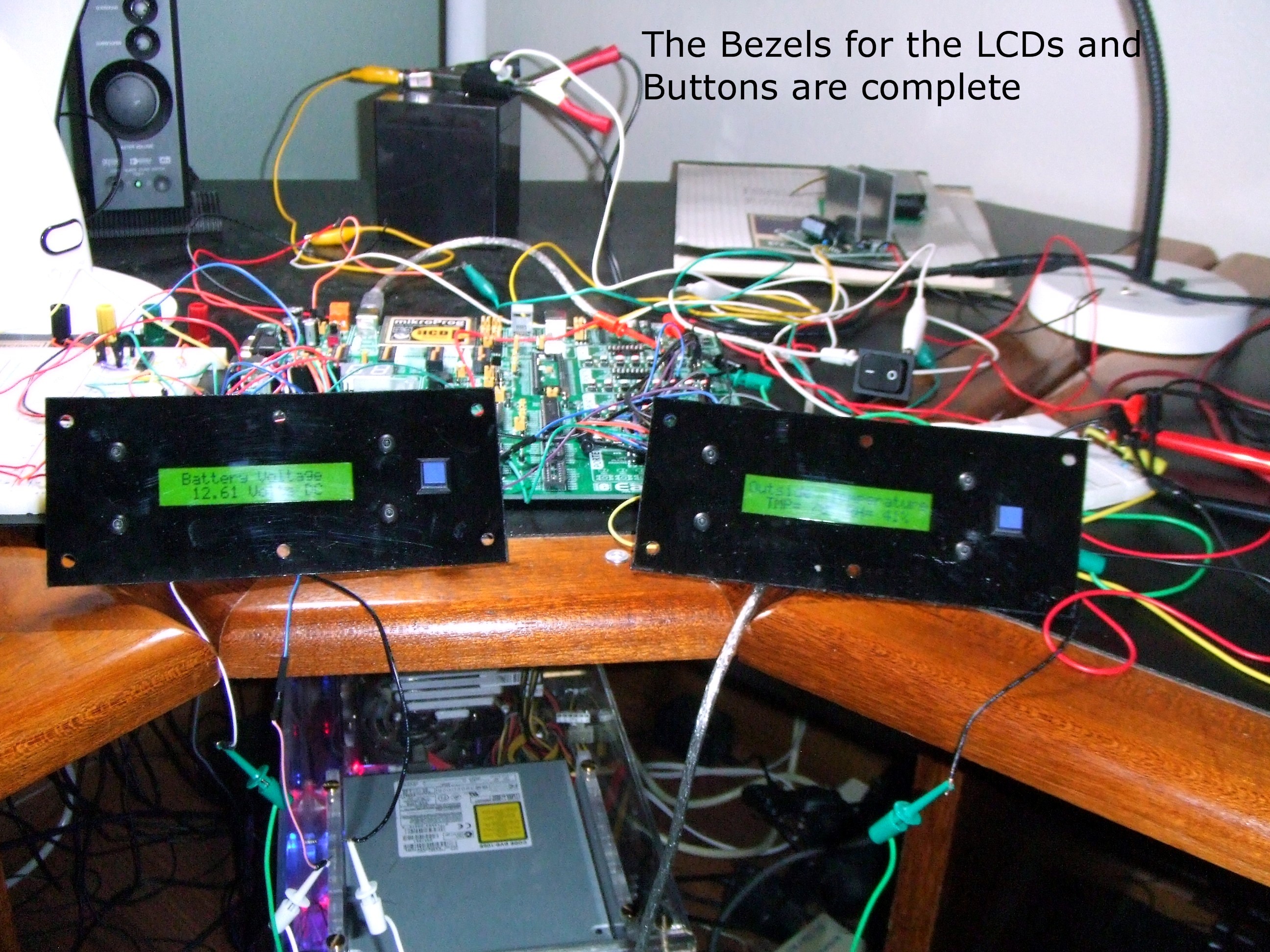
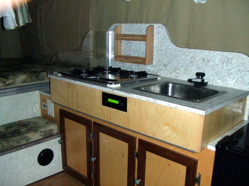
I did manage to fab and install the Bezels for the LCDs and buttons. It's just Plexiglas painted on the back side but looks pretty good.
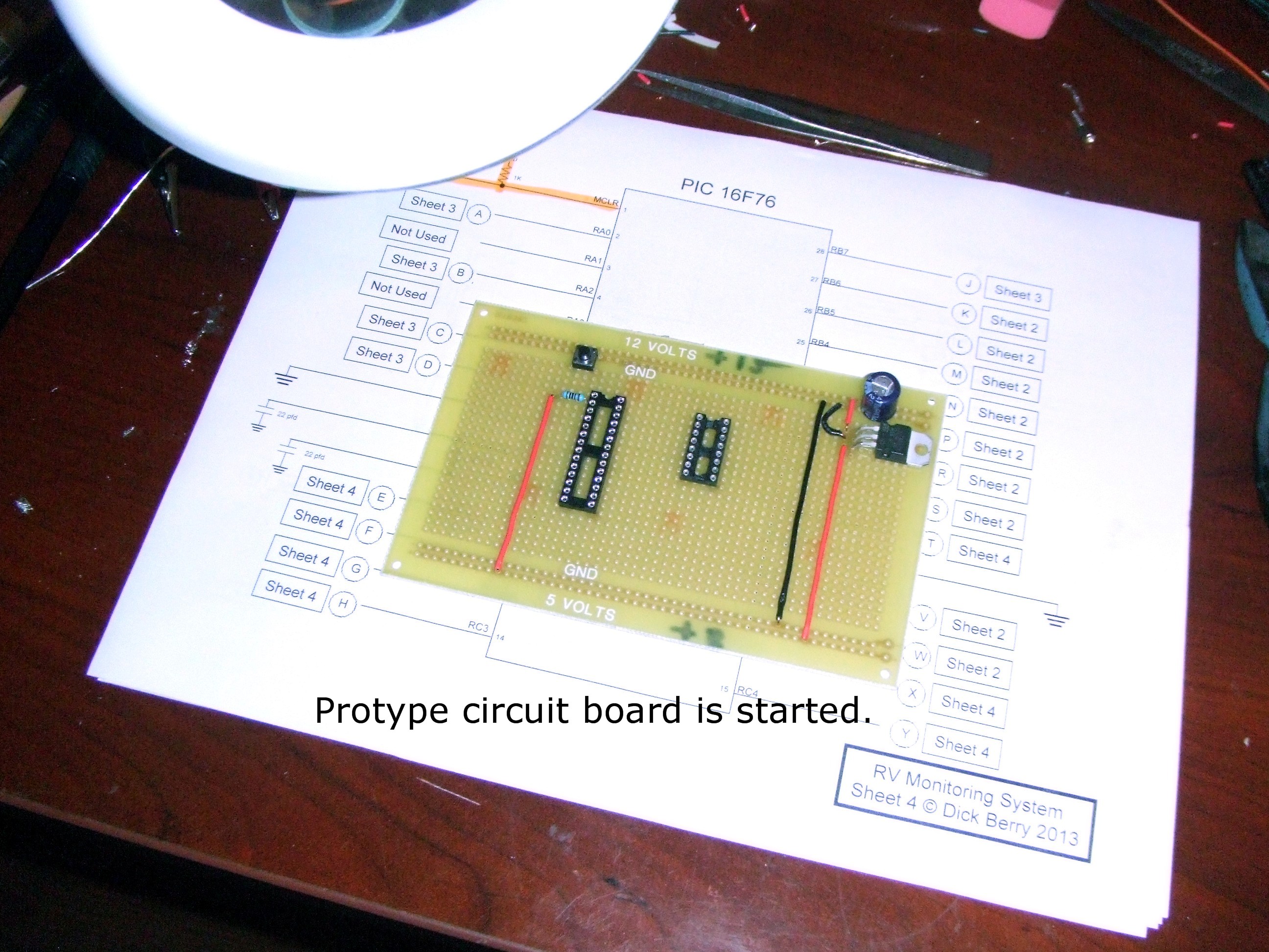
Also I've started the build of the prototype circuit board. Not much done yet but it's a start.
Here are a few pictures of what I have so far. I'll post updated software after I've fine tuned the DHT22 com timing with a scope.
Thanks for looking.
Dick

I have the coms working but get more errors than I like. This test is counting the errors. After I get my scope I'll be able to fine tune the timing and hopefully reduce the error count.
View full image
These Bezels are Plexiglas painted on the back. I really should have cleaned off the dust before taking the pictures.
View full image
Not much but it's a start. These old eyes have problems with this small stuff so I need to go slowly and check for shorts often.
View full imageUpdate 6/25/2013
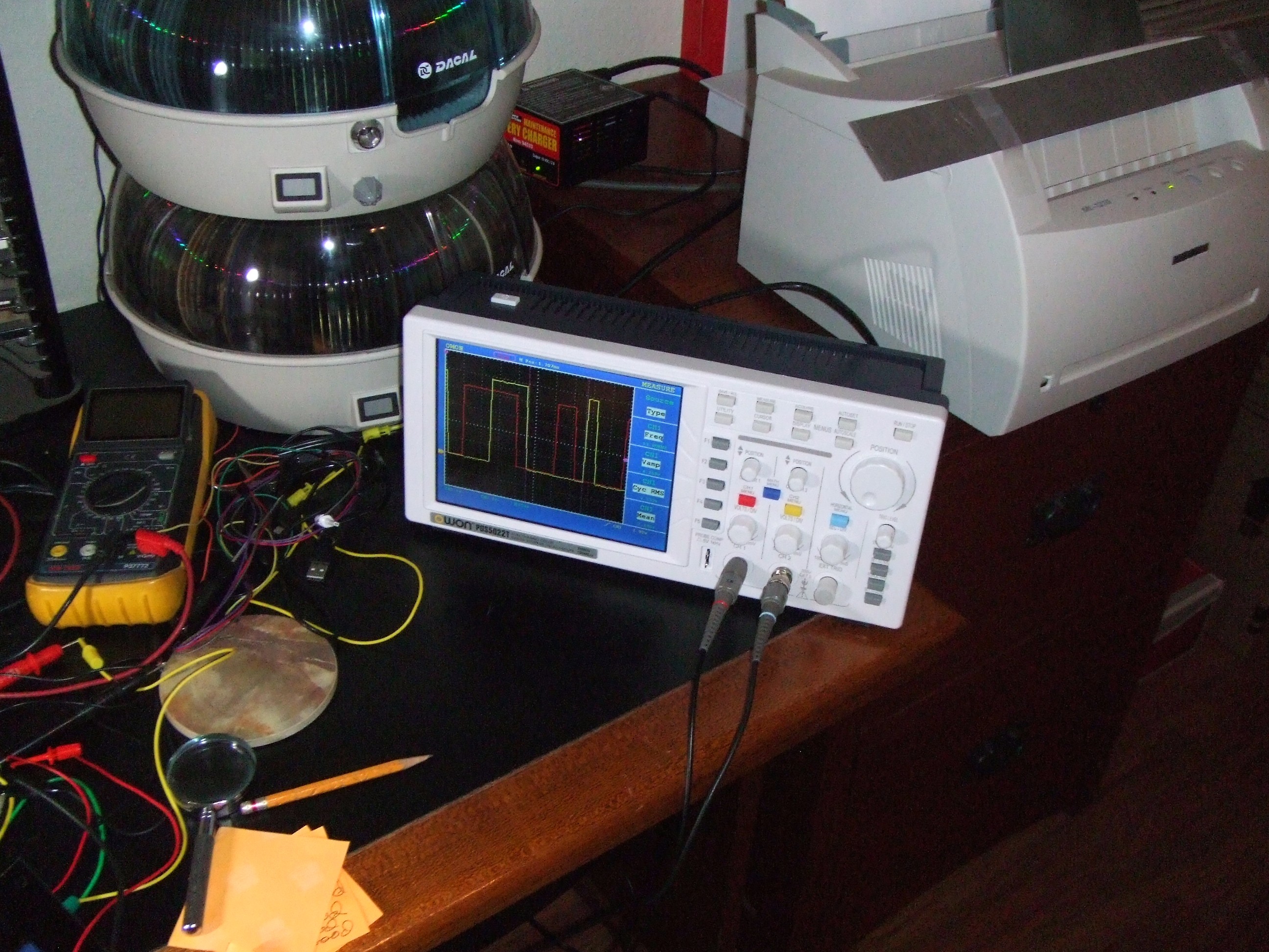
Got the new Scope yesterday. It's the low end but does 25 MHZ so it's plenty for my projects.
I was able to refine the data capture from the DHT22. I installed a delay in the One (1) Bits so I'm guaranteed to start the loop in the next start bit. Also I disabled Interrupts in the capture routine which made it a lot more consistent. The error count is down but I'm still going to change it to use counter Zero to measure the bit time. I figured out how to get it counting at a 1 usec rate so the delta between a Zero and a One will be easy to detect. This method will start me as far left in the Start bit as possible which is one of my problems. To get the data logged and For Loops counted I was not getting back to the top in time and got hung up looking for the start bit when in reality I was in the data bit. This was especially true when the Interrupt routine took some of my time. I was a little surprised because I'm running the 16F76 at 16 MHZ. It's just that the timing for the DHT22 is in the Micro Secs and there isn't a lot of time even at 16 MHZ.
Here are some pictures of the Data Stream and the Scope in general. I like the Scope. It's intuitive to use and unlike others I've seen very reliable at triggering. BTW it's a OWON PDS5022T.
Thanks For Looking
Dick


I had a little space next to the development board.
View full image
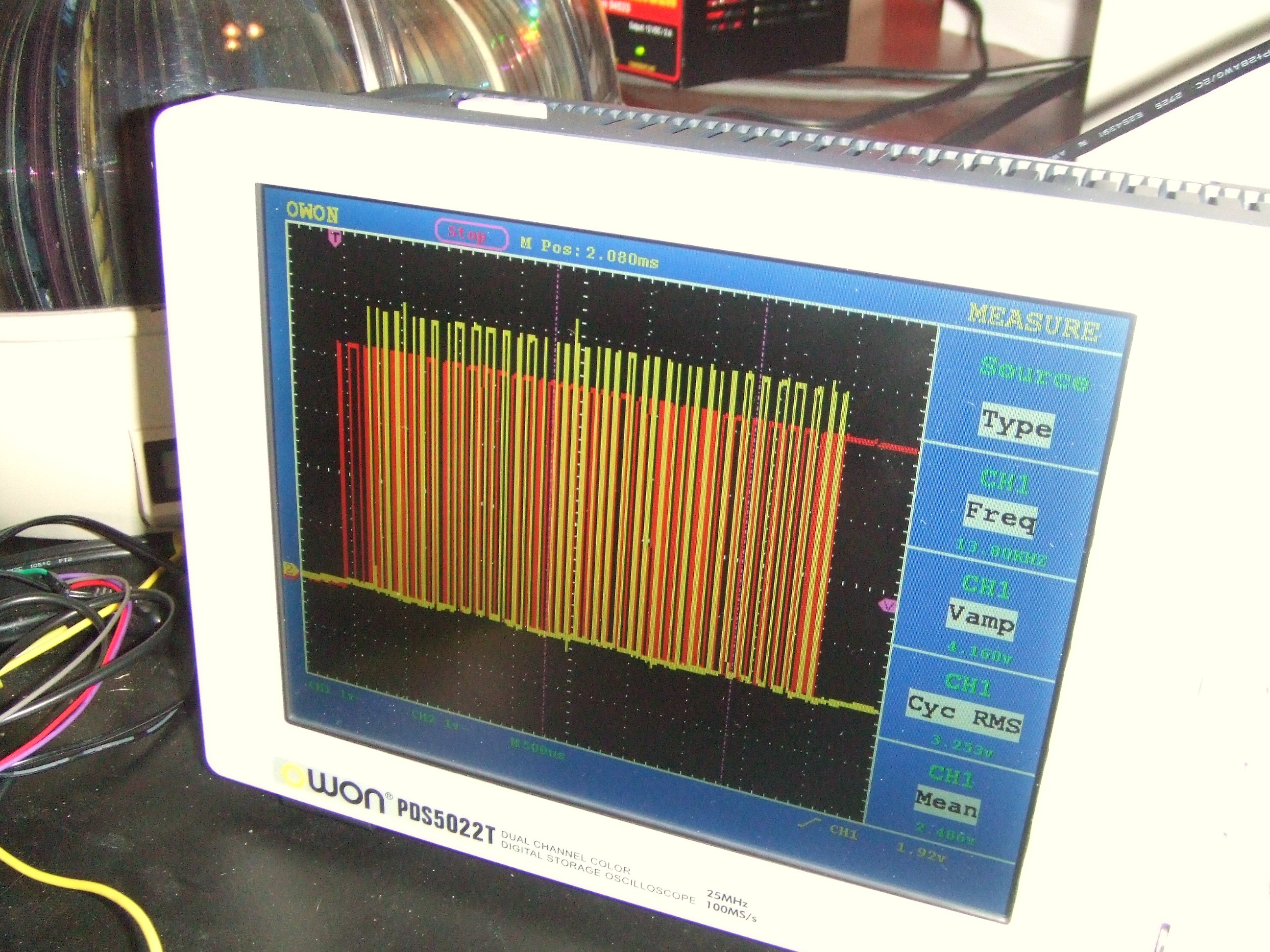
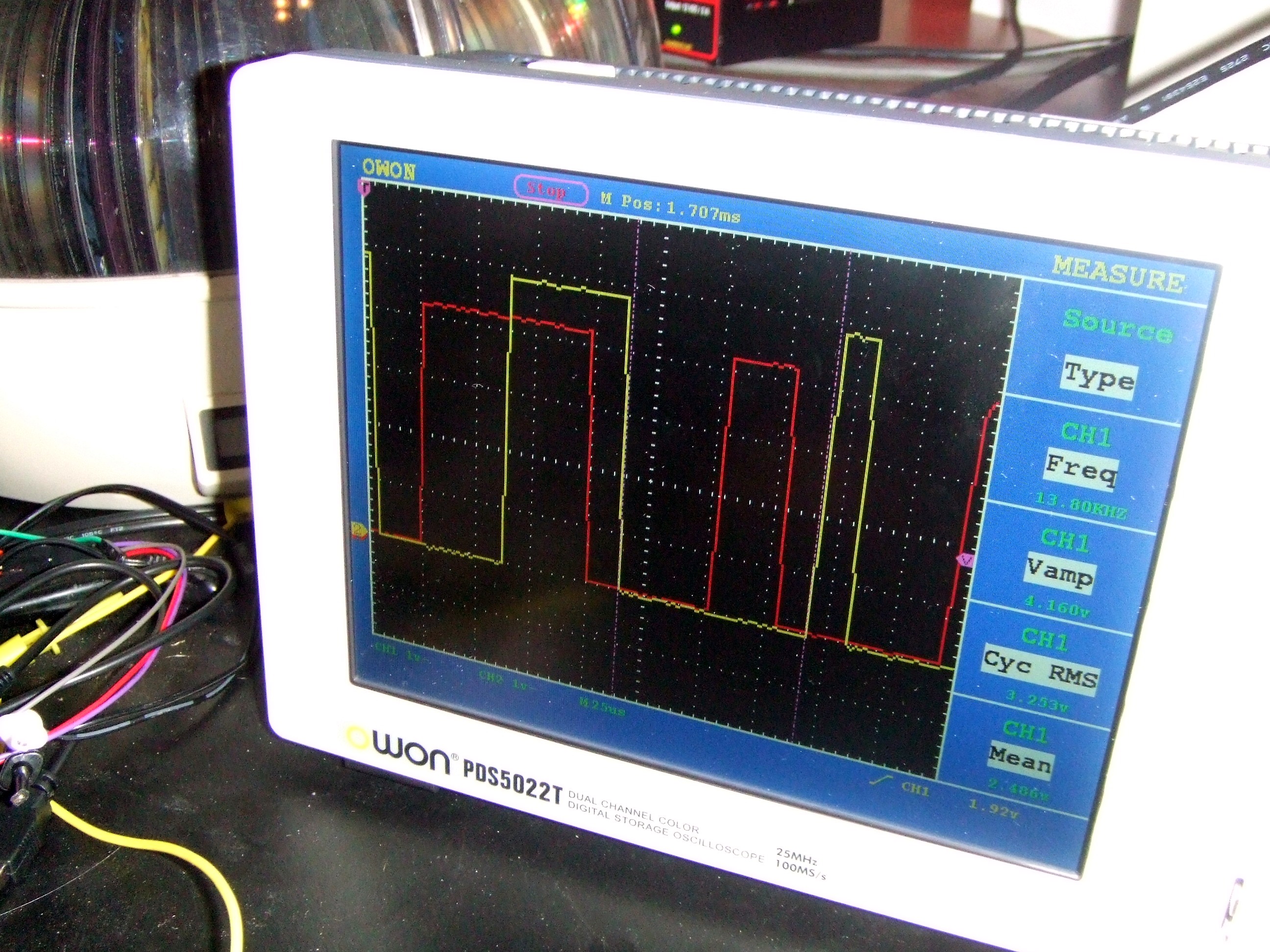
All five bytes in this image. Not good for analyzing, but good for overall time required.
View full image
The red trace is the data from the DHT22. The yellow trace is a bit on PortC I twiddled to see capture position and placement in the start bit for the next bit.
View full image
Updata 6/26/2013 10:15 PM
This is Revision 2. I changed the Temp sensors to AM2303 to Get Temp and Humidity. The Deg. "C" to Deg. "F" conversion covers -4C to 124C. I hope I never see those numbers while camping. I am using Timer0 to detect errors and measure the Data Bit time. I haven't seen any code in MBasic for reading these devices so here it is. I tried using Delays for the measurement but it was unrealible, this method works much better. I have been running it for about 24 Hours now with no errors at all. I'll include a link to a short Video. The comments describe what I've done pretty well.
Here is a link to a short demo video. It's case sensitive
I can't seem to get the link to work with the insert video button.
Thanks For Looking
Dick
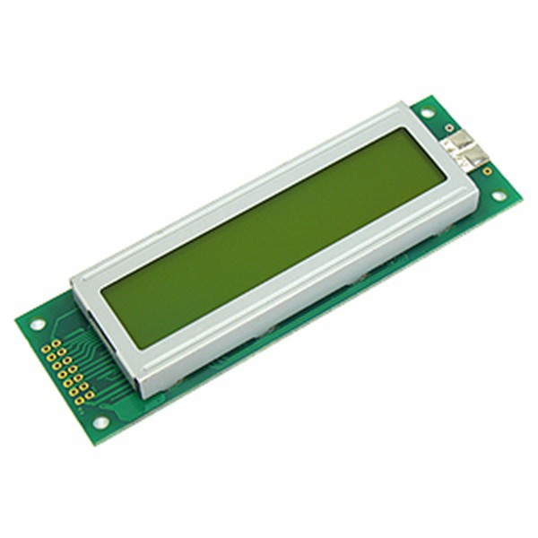
BTW The Electronic Goldmine has these LCD Displays on sale for $1.49. I Don't know how long it will last, but if yoy could uses some, they work fine with the EasyPic V7, both the hardware interface and the LCD Libraries.
http://www.goldmine-elec-products.com/prodinfo.asp?number=G19319
Dick

The backlight takes a bit of current @ 100MA but it has a nice green glow. Dick
View full imageI realized that six water sensors for a 12 Gal tank is just too many. So now I've changed to also display the water level in the gray tank. I'll have three sensors in each tank.
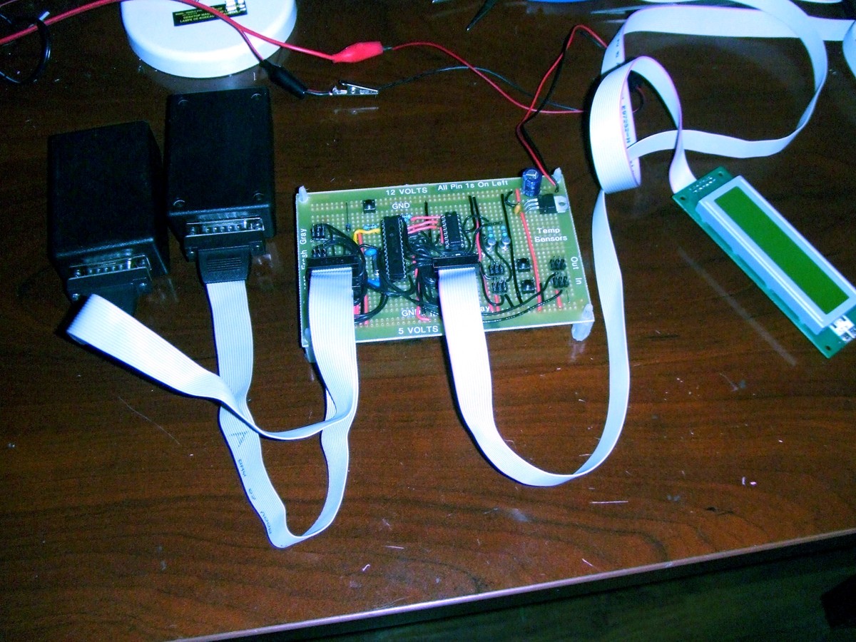
The prototype board is completed and tested. Everything is on connectors so I can pull out any of the elements without removing cables. I made up some pretty long cables for the displays just to be sure I won't need drivers when installed in my Pop Up. All is working well.
Here are a few pictures.
Thanks for looking
Dick

The boxes on the left are the water sensor kits. Either box can be for Fresh or gray. They are identical.
View full image
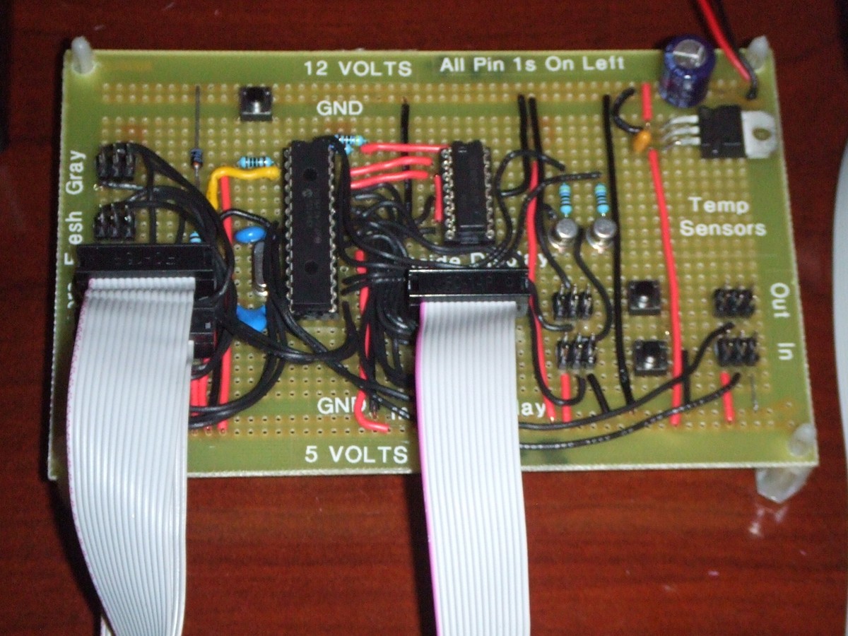
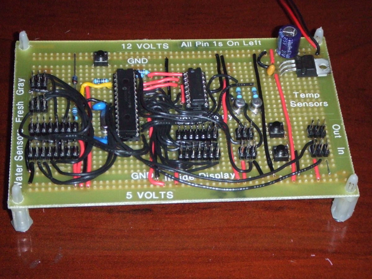
A closer look at the board with the water sensor boxes and one display installed.
View full image
The three rows on the right are for, bottom row inside Temp Sensor, Six pin connector is for the backlight and the 14 pin is for the display. The row just above it are the same connectors for the outside modules. I added two buttons between the Temp
View full image
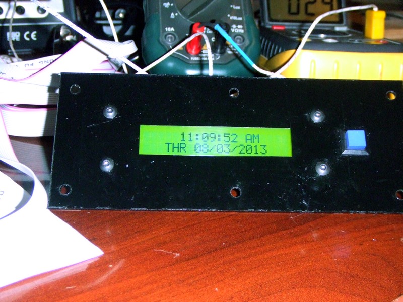
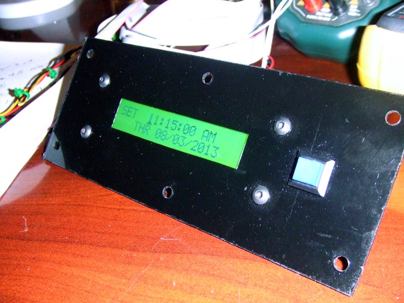
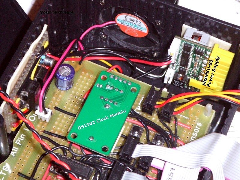
Version 4 Adds a Time Of Day Clock. I chose a DS1302 chip because it isn't I2C and allowed me more freedom choosing I/O Pins. The Alarm is installed and alerts when the Battery is Low.
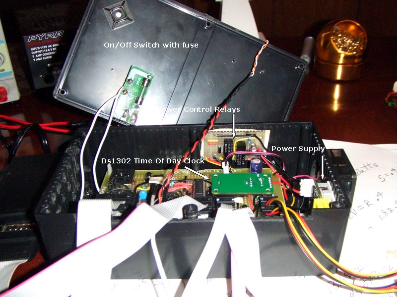
I also changed the Power Supply. I measured the Temp on the regulator and found it to be nearly 200 F. In the great outdoors this would be even higher. The total current was approaching 400 MA out of the Battery. So I changed to a picoPSU-80 Power Module. It's very efficient at 94% below 1 AMP draw so there is really no heat in the box. I now measure about 3 Deg. C heat rise from ambient. The current draw from the battery is also down to 230MS worst case with the more efficient PS. This Supply Crowbars on high voltage so I added a Diode drop in the feed line to be able to have the battery just a touch higher. I found that when the PS Crowbars the +5 VDC doesn't go to zero and hangs around 3.2 VDC. This is a problem with the battery voltage at max into the A to D RA1. The PIC spec no more than .3 Volts higher than VDD. So since the PS is designed for small Computers it has a Power Good line output. I used this output to control two relays that completely turn off both the VDD and Battery feeds and this is working very well.
I finally had to deal with the high Ram Bank. I put all the Text in CONST declarations and moved them to a Print Buffer in the high RAM Bank and printed from there. It was easy to manage the IRP_Bit and kept all the management in the Sub_Routine Module.
I've got more but the system just won't add it. I'll try again tomorrow.
Thanks for Looking
Dick
Some more testing and I can install it in may camper. It's stable now and I have tested for three days now without any anomalies. So I believe it's done. I'm out of I/O and Ram. I'd have to change processors to do any more and I can't think of anything else I'd want.
As a side note: I had a failure in my EasyPic V7 that completely disabled programming. Working with Customer Support at MikroElectronica I was able to determine the problem was U10 Voltage Translator in the programmer. It's located under the can. I found a new one at Mouser and replaced it and now all is well. Just wanted to give a shout out to Marina over in support. She stayed with me all the way and was very helpful. In fact without her help I would have never gotten it fixed.
Be sure to read the Design Doc to see how I solved the problem of setting the clock with only one button for input.
Thanks for Looking
Dick


A real challenge to set the time and date with only one button. See requirements document for instructions.
View full image

The original regulator was getting very hot so I changed it out for a picoPSU-80 power supply that is 94% efficient and it all stays very cool now.
View full image
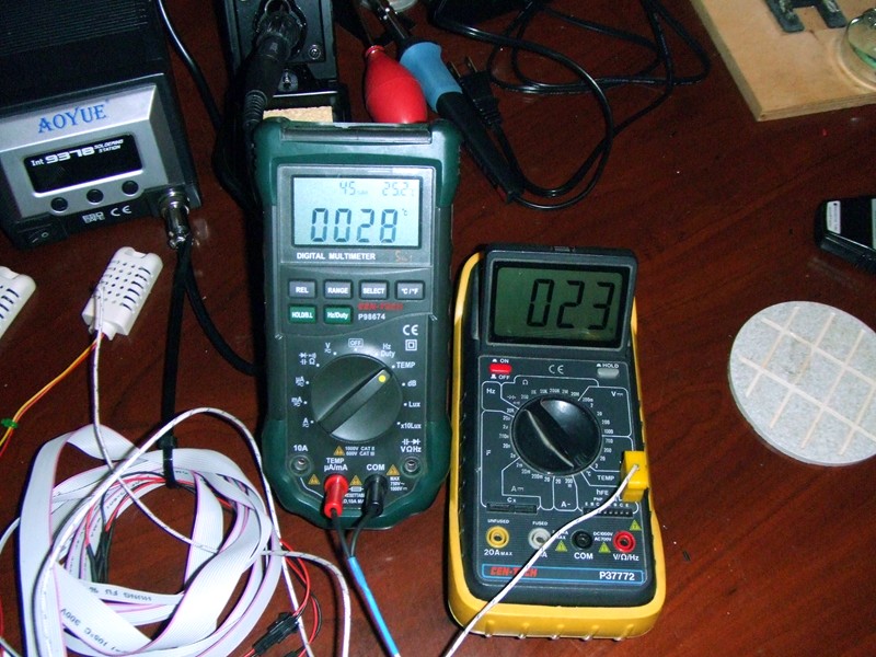
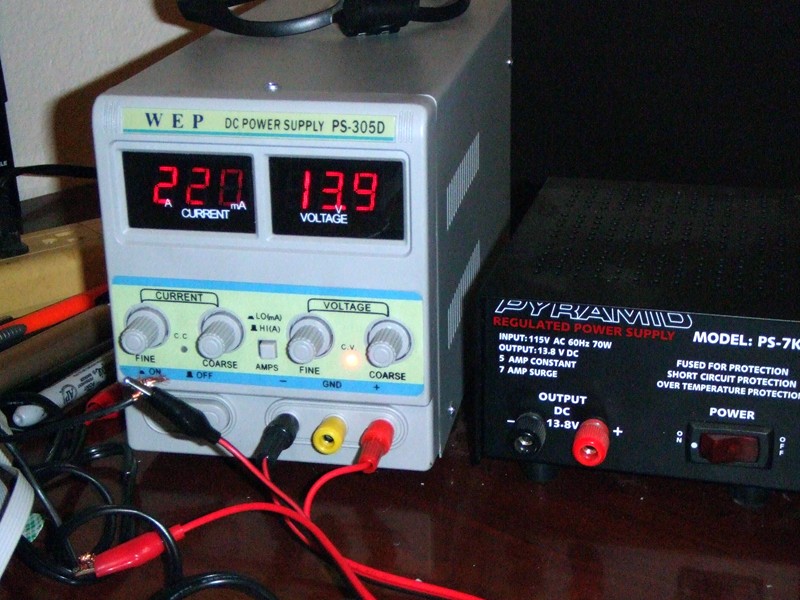
The yellow meter is ambient temp and the green on is on the processor. My temp rise is now in acceptable limits.
View full image
Before the Power Supply change this would have been almost 400 ma, but now this is the worst case.
View full image
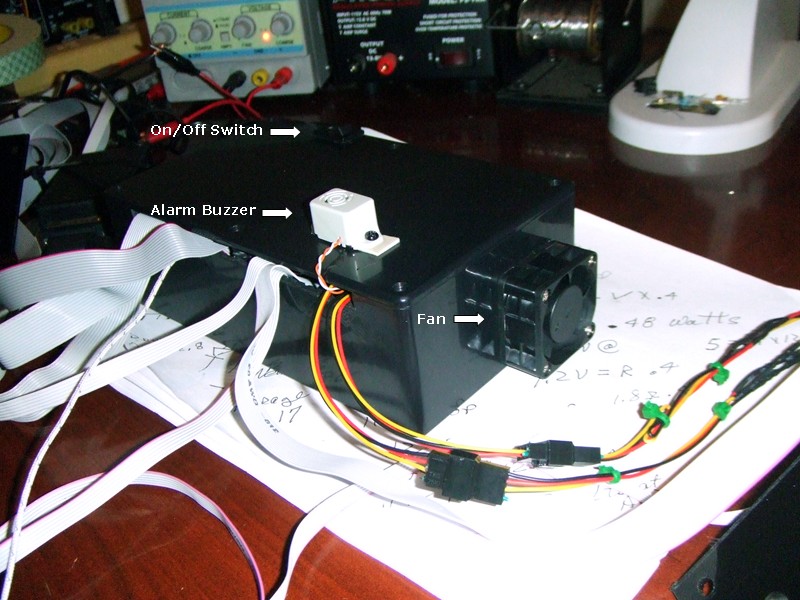
This supply is really worth the effort. It's 80 Watts, more than this little guy will ever need. Being designed for PC Mother Boards it has a Power Good signal that I used to control power to the board. It also has Low and High Voltage protection. Just th
View full image
It's all installed now. Here is a link to some pictures of the Pop Up with the system installed. It's working fine and version four is the final version.
https://skydrive.live.com/?cid=ae67fff392766057#cid=AE67FFF392766057&id=AE67FFF392766057%215095&v=3
We did the remodel last winter. This is a 1977 Palomino Yearling Pop Up Camper a real oldie but goodie.
Thanks for looking
Dick

WOW Downloaded: 255 times that's eight bits worth.
Really just trying to bump this on the home page ;-)
Dick


