TOP Contributors

  1. MIKROE (2650 codes)
  2. Alcides Ramos (350 codes)
  3. Shawon Shahryiar (307 codes)
  4. jm_palomino (112 codes)
  5. Chisanga Mumba (90 codes)
  6. S P (73 codes)
  7. dany (71 codes)
  8. MikroBUS.NET Team (35 codes)
  9. NART SCHINACKOW (34 codes)
  10. Armstrong Subero (27 codes)

Most Downloaded

  1. Timer Calculator (136549 times)
  2. FAT32 Library (69742 times)
  3. Network Ethernet Library (55847 times)
  4. USB Device Library (46184 times)
  5. Network WiFi Library (41803 times)
  6. FT800 Library (40993 times)
  7. GSM click (28926 times)
  8. PID Library (26385 times)
  9. mikroSDK (26288 times)
  10. microSD click (25301 times)
Libstock prefers package manager

Package Manager

We strongly encourage users to use Package manager for sharing their code on Libstock website, because it boosts your efficiency and leaves the end user with no room for error. [more info]

< Back
mikroSDK Library

OSD click

Rating:

0

Author: MIKROE

Last Updated: 2019-07-30

Package Version: 1.0.0.1

mikroSDK Library: 1.0.0.0

Category: OSD

Downloaded: 6862 times

Followed by: 1 user

License: MIT license  

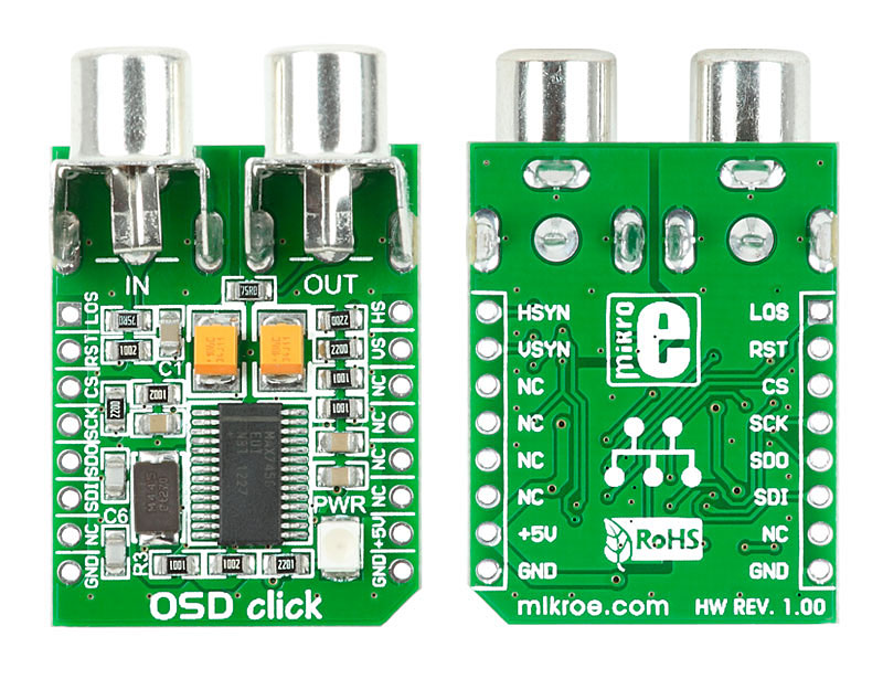
This is a sample program which demonstrates the use of OSD click.
Program shows the time and date in corners of the screen and enable you to set the time and date, using the OSD menu.

No Abuse Reported

Do you want to subscribe in order to receive notifications regarding "OSD click" changes.

Do you want to unsubscribe in order to stop receiving notifications regarding "OSD click" changes.

Do you want to report abuse regarding "OSD click".

  • mikroSDK Library 2.0.0.0
  • Comments (2)
DOWNLOAD LINK RELATED COMPILER CONTAINS
mikroBasic PRO for ARM
  • lib
  • src
  • exa
  • hlp
  • hex
  • sch
  • pcb
  • doc
mikroBasic PRO for AVR
  • lib
  • src
  • exa
  • hlp
  • hex
  • sch
  • pcb
  • doc
mikroBasic PRO for dsPIC30/33 & PIC24
  • lib
  • src
  • exa
  • hlp
  • hex
  • sch
  • pcb
  • doc
mikroBasic PRO for FT90x
  • lib
  • src
  • exa
  • hlp
  • hex
  • sch
  • pcb
  • doc
mikroBasic PRO for PIC
  • lib
  • src
  • exa
  • hlp
  • hex
  • sch
  • pcb
  • doc
mikroBasic PRO for PIC32
  • lib
  • src
  • exa
  • hlp
  • hex
  • sch
  • pcb
  • doc
mikroC PRO for ARM
  • lib
  • src
  • exa
  • hlp
  • hex
  • sch
  • pcb
  • doc
mikroC PRO for AVR
  • lib
  • src
  • exa
  • hlp
  • hex
  • sch
  • pcb
  • doc
mikroC PRO for dsPIC30/33 & PIC24
  • lib
  • src
  • exa
  • hlp
  • hex
  • sch
  • pcb
  • doc
mikroC PRO for FT90x
  • lib
  • src
  • exa
  • hlp
  • hex
  • sch
  • pcb
  • doc
mikroC PRO for PIC
  • lib
  • src
  • exa
  • hlp
  • hex
  • sch
  • pcb
  • doc
mikroC PRO for PIC32
  • lib
  • src
  • exa
  • hlp
  • hex
  • sch
  • pcb
  • doc
mikroPascal PRO for ARM
  • lib
  • src
  • exa
  • hlp
  • hex
  • sch
  • pcb
  • doc
mikroPascal PRO for AVR
  • lib
  • src
  • exa
  • hlp
  • hex
  • sch
  • pcb
  • doc
mikroPascal PRO for dsPIC30/33 & PIC24
  • lib
  • src
  • exa
  • hlp
  • hex
  • sch
  • pcb
  • doc
mikroPascal PRO for FT90x
  • lib
  • src
  • exa
  • hlp
  • hex
  • sch
  • pcb
  • doc
mikroPascal PRO for PIC
  • lib
  • src
  • exa
  • hlp
  • hex
  • sch
  • pcb
  • doc
mikroPascal PRO for PIC32
  • lib
  • src
  • exa
  • hlp
  • hex
  • sch
  • pcb
  • doc

mikroSDK Library Blog

OSD click

OSD click

Front and back side appearance of the OSD click Board.

View full image

Library Description

The library covers all the necessary functions to control OSD click board. The library performs the communication with the device via SPI protocol by writing to registers and by reading from registers.

Key functions:

  • void osd_writeByte( uint8_t regAddress, uint8_t writeData ) - Write the byte of data function.
  • uint8_t osd_readByte( uint8_t regAddress ) - Read the byte of data function.
  • void osd_writeCharacter( uint8_t linePos, uint8_t rowPos, uint8_t symbol ) - Write a character by position function.

Examples description

The application is composed of the three sections :

  • System Initialization - Initializes SPI and LOG structures sets AN, INT and PWM pins as input, set RST and CS pins as output and start to write log.
  • Application Initialization - Initialization driver enables - SPI, the set default configuration, clears all character places, also write log.
  • Application Task - This is an example which demonstrates the use of OSD Click board. In this example, we write text on the screen, write character per 1 second in the first, seventh and fifteenth row of the screen.
void applicationTask()
{
    for ( cnt = 0; cnt < 30; cnt++ )
    {
        if( HEADER_TEXT[ cnt ] != ' ' )
        {
            osd_writeCharacter( 1, cnt, HEADER_TEXT[ cnt ] );
        }

        if( MESSAGE_TEXT[ cnt ] != ' ' )
        {
            osd_writeCharacter( 7, cnt, MESSAGE_TEXT[ cnt ] );
        }

        if( FOOTER_TEXT[ cnt ] != ' ' )
        {
            osd_writeCharacter( 14, cnt, FOOTER_TEXT[ cnt ] );
        }

        Delay_1sec();
    }

    osd_clearsCharPlaces( 0, 0, 16, 30 );
    Delay_1sec();
}

Other mikroE Libraries used in the example:

  • SPI
  • UART

Additional notes and informations

Depending on the development board you are using, you may need USB UART clickUSB UART 2 click or RS232 click to connect to your PC, for development systems with no UART to USB interface available on the board. The terminal available in all MikroElektronika compilers, or any other terminal application of your choice, can be used to read the message.

ALSO FROM THIS AUTHOR

Step Down 3 click

0

Step Down 3 Click is a compact add-on board that steps down the voltage from its input to its output. This board features the ST1PS03, a nano-quiescent miniaturized synchronous step-down converter with a load switch from STMicroelectronics. The ST1PS03 can provide up to 400mA output current with an input voltage ranging from 1.8V to 5.5V, specifically designed for applications where high efficiency is crucial. It also embeds a controlled switch accessible from auxiliary channel input to supply a subsystem, output voltage from 1.6V to 3.3V set using three digital control inputs, and a Power Good signal to indicate stabilized output voltages.

[Learn More]

7x10 Y click

0

7x10 Y click is a LED dot matrix display click, which can be used to display graphics or letters in a very simple and easy way. The click board has two LED dot matrix modules with 7x5 stylish, round, dot-like LED elements. These displays produce clean and uniform patterns since the elements are optically isolated from each other and there is no light bleeding between the adjacent LED cells. Additionally, turn-on and turn-off times of the matrix cells are optimized for a clean and fluid display performance, with no flickering or lag.

[Learn More]

M-Bus Master click

0

The M-Bus Master is a Click board™ is complete solution for a master node in M-Bus networks.

[Learn More]