20%

We strongly encourage users to use Package manager for sharing their code on Libstock website, because it boosts your efficiency and leaves the end user with no room for error. [more info]

Rating:
Author: VCC
Last Updated: 2023-12-31
Package Version: 1.0.0.0
Category: Measurement
Downloaded: 60 times
Not followed.
License: MIT license
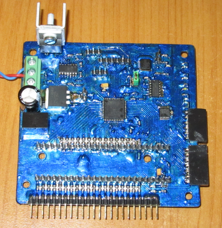
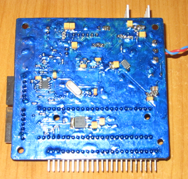
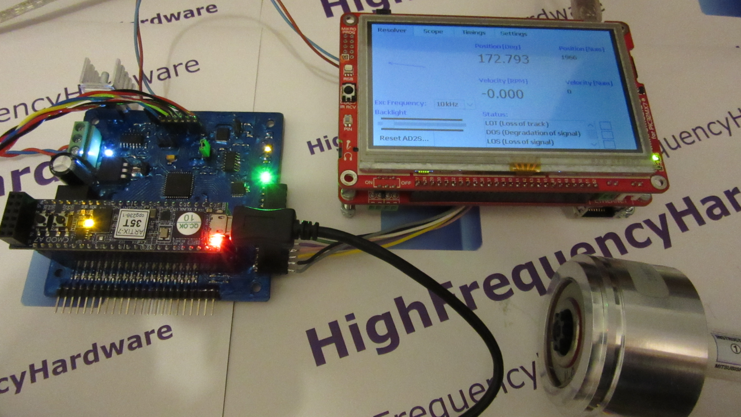
ResolverAD2S1200DecA7 is a hardware + software project, which uses AD2S1200 chip, to interface with a resolver, for motor control applications.
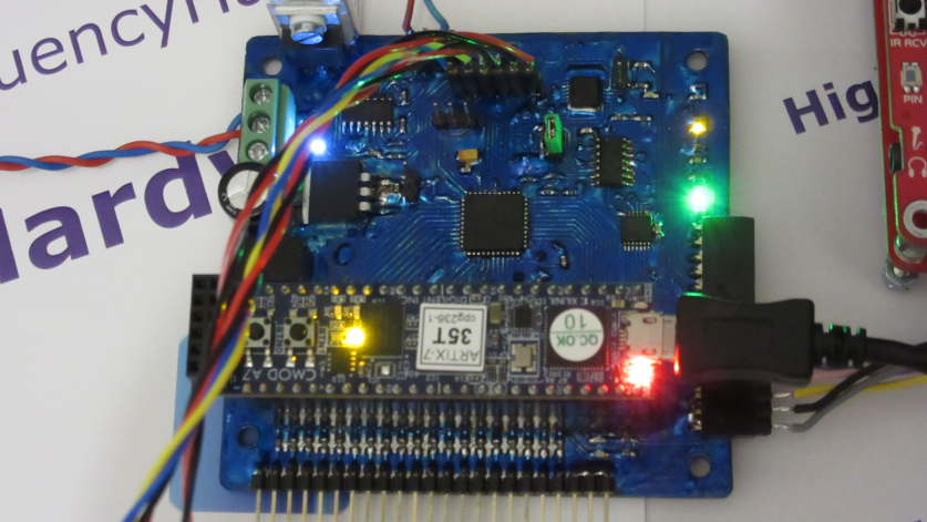
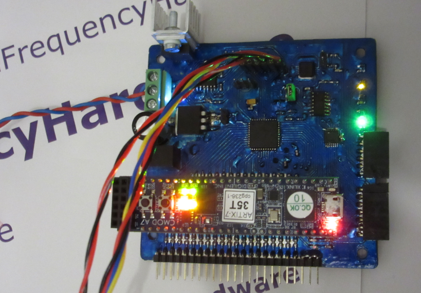
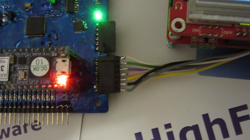
To talk to the AD2S1200 chip, the Digilent's CmodA7 board is used.
Do you want to subscribe in order to receive notifications regarding "Resolver connected to AD2S1200 decoder with CmodA7 board" changes.
Do you want to unsubscribe in order to stop receiving notifications regarding "Resolver connected to AD2S1200 decoder with CmodA7 board" changes.
Do you want to report abuse regarding "Resolver connected to AD2S1200 decoder with CmodA7 board".
| DOWNLOAD LINK | RELATED COMPILER | CONTAINS |
|---|---|---|
| 1636041210_resolver_connect_mikropascal_pic32.zip [2.48MB] | mikroPascal PRO for PIC32 |
|
ResolverAD2S1200DecA7 is a hardware + software project, which uses AD2S1200 chip, to interface with a resolver, for motor control applications.
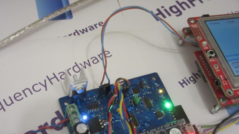
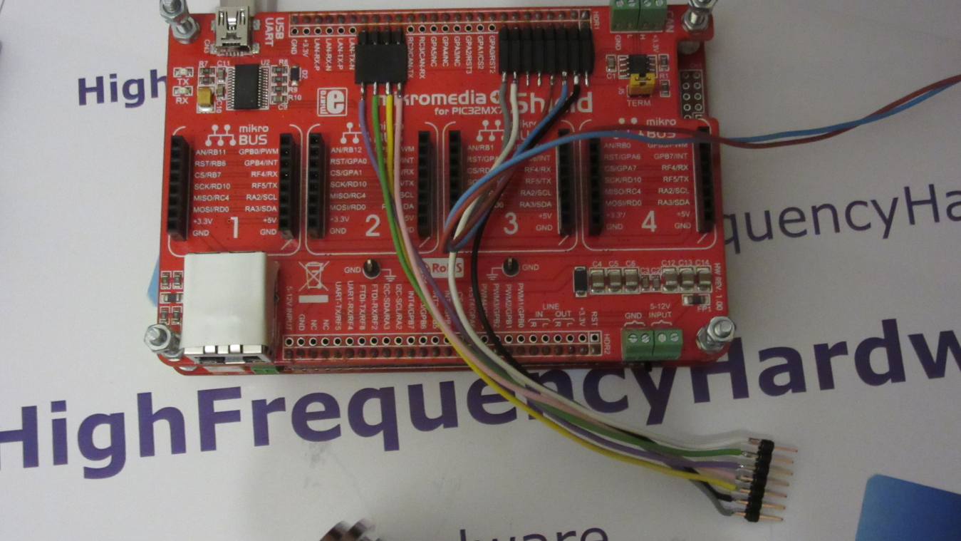
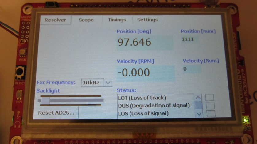
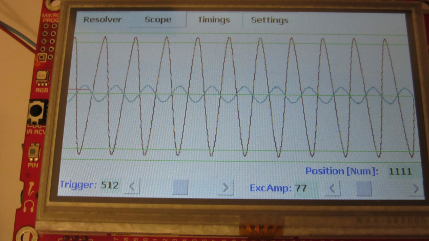
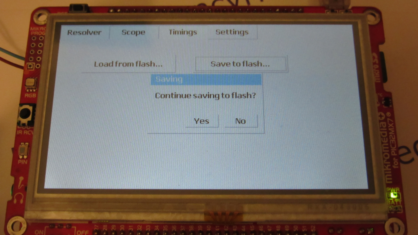
To talk to the AD2S1200 chip, the Digilent's CmodA7 board is used. A PIC32 application, on mikroe's mikroMedia for PIC32MX7+ board, provides an UI for setting various working parameters, measurements and debugging.
Requirements:
- mikroMedia for PIC32MX7+ board
- CmodA7 board: https://digilent.com (CmodS6 is hardware compatible)
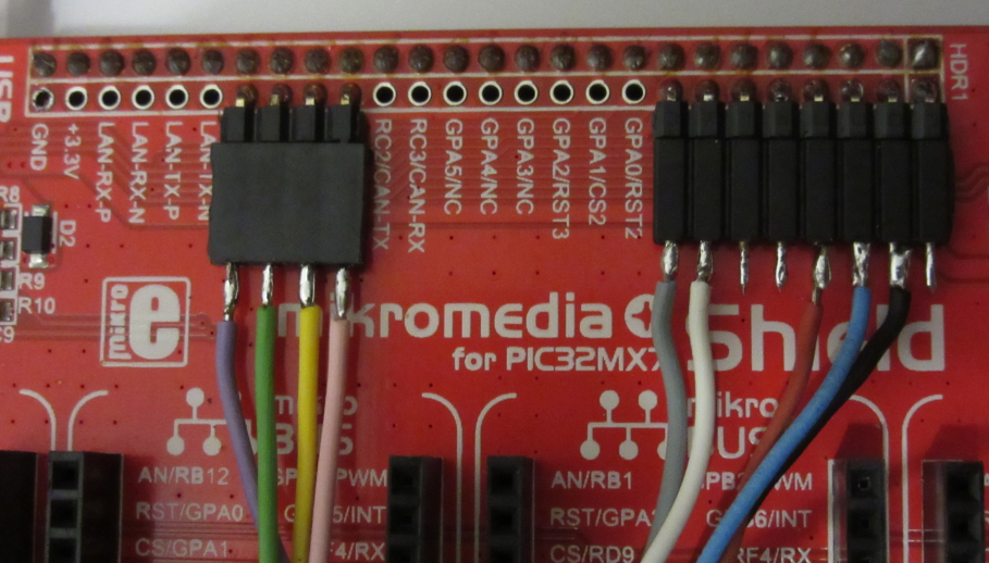
The CmodA7 board, directly plugs into the AD2S board (Cmod USB connector towards connector P3 on AD2S board).
- building the board, with the design from HW directory
See ReadMe.txt for details.


")


")


Known issues
- The operational amplifier, ALM2402, which drives the resolver signals, is limited to about 12kHz.
Because of that limit, the ALM2402F version should be used (see their datashets on https://ti.com).
The ALM2402 version (without "F") may still be used on lower resolver velocities, because of low frequency signals.
At higher frequencies, like 15kHz, or 20kHz (as generated by AD2S1200), the signals become distorted and attenuated.
In that case, AD2S1200 enters error mode, so the FPGA application continously resets it.
- The series resistors, between the FPGA board and the AD2S1200 chip, will affect communication speed,
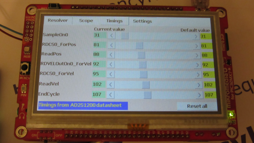
thus various timing parameters may need to be manually adjusted (see PIC32 UI, the AD2S1200 datasheet and \FPGA\src\vhdl\Common\AD2S1200Interface.vhd)
The velocity reading may constantly change (by one LSB), even on no resolver movement or constant velocity. This does't seem to come from bad timing.


