
We strongly encourage users to use Package manager for sharing their code on Libstock website, because it boosts your efficiency and leaves the end user with no room for error. [more info]

Rating:
Author: MIKROE
Last Updated: 2012-12-14
Package Version: 1.0.0.0
Category: Timers (Real time clock)
Downloaded: 3689 times
Not followed.
License: MIT license
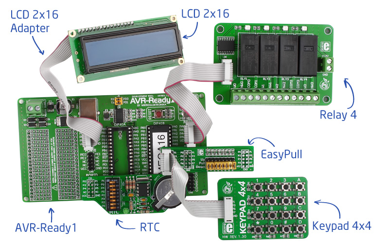
Build your own programmable timer relays using AVR-Ready1, Keypad 4x4 board with EasyPull, RTC, Relay 4 and LCD 2x16 character display with adapter. Just load the demonstration project code and your device is ready to control 4 separate relays.
Do you want to subscribe in order to receive notifications regarding "Programmable Relay Timers (AVR)" changes.
Do you want to unsubscribe in order to stop receiving notifications regarding "Programmable Relay Timers (AVR)" changes.
Do you want to report abuse regarding "Programmable Relay Timers (AVR)".
| DOWNLOAD LINK | RELATED COMPILER | CONTAINS |
|---|---|---|
| 1313653218_programmable_rel.zip [2.05MB] | mikroC PRO for AVR |
|
| 1313653276_programmable_rel.zip [2.05MB] | mikroBasic PRO for AVR |
|
| 1313653340_programmable_rel.zip [2.05MB] | mikroPascal PRO for AVR |
|

Washing machines, electric ovens, garden sprinklers, TV and even home bakeries all have a programmable delay operation. We will show you how you can build your own programmable relay timers with mikroElektronika boards in less than 30 seconds. Just connect AVR-Ready1, Keypad 4x4 board with EasyPull, RTC, Relay 4 and LCD 2x16 character display with adapter and load demonstration project code and your device is ready to rock! It can control 4 separate relays
Project has numerous applications. We only suggest several:
We are sure that you will find much more possible applications. Don’t
hesitate to send us photos of what you have built using this project
kit.

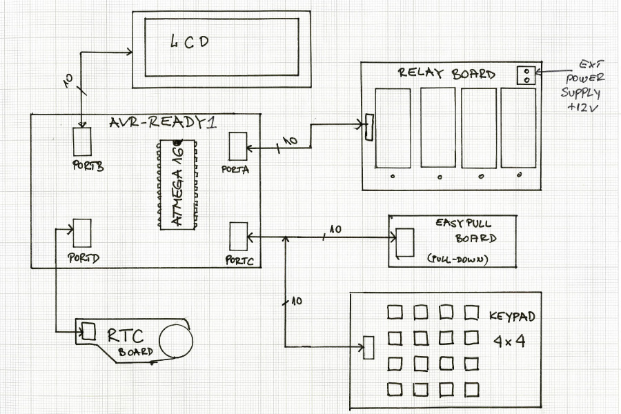
Programmable Relay Timers schematics
View full imageSource code of this project is provided for free, so you can modify it to suit your needs. Since ATMega16 comes preprogrammed with free UART Bootloader, you won’t have to spend a dollar more on external programmers. You can modify the project as much as you like, and expand this basic functionality with your own implementation ideas.


