TOP Contributors

  1. MIKROE (2656 codes)
  2. Alcides Ramos (354 codes)
  3. Shawon Shahryiar (307 codes)
  4. jm_palomino (112 codes)
  5. Chisanga Mumba (90 codes)
  6. S P (73 codes)
  7. dany (71 codes)
  8. MikroBUS.NET Team (35 codes)
  9. NART SCHINACKOW (34 codes)
  10. Armstrong Subero (27 codes)

Most Downloaded

  1. Timer Calculator (136888 times)
  2. FAT32 Library (70022 times)
  3. Network Ethernet Library (56002 times)
  4. USB Device Library (46308 times)
  5. Network WiFi Library (41934 times)
  6. FT800 Library (41209 times)
  7. GSM click (29017 times)
  8. PID Library (26432 times)
  9. mikroSDK (26399 times)
  10. microSD click (25386 times)
Libstock prefers package manager

Package Manager

We strongly encourage users to use Package manager for sharing their code on Libstock website, because it boosts your efficiency and leaves the end user with no room for error. [more info]

< Back
mikroSDK Library

H-Bridge 6 click

Rating:

5

Author: MIKROE

Last Updated: 2021-08-06

Package Version: 1.0.0.0

mikroSDK Library: 1.0.0.0

Category: Brushed

Downloaded: 1201 times

Not followed.

License: MIT license  

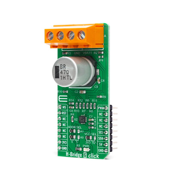
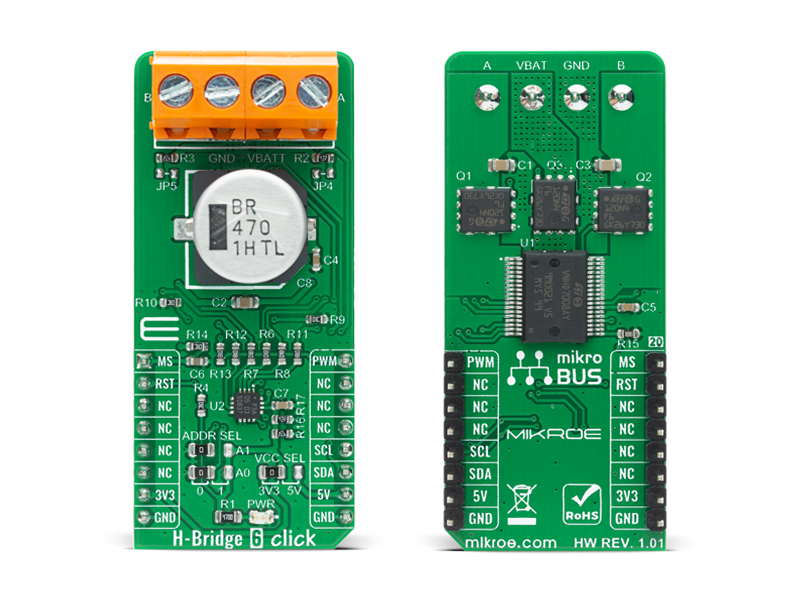
H-Bridge 6 Click is a compact add-on board that contains a DC motor driver for automotive applications. This board features the VNHD7008AY, an H-bridge motor driver for automotive DC motor driving from STMicroelectronics.

No Abuse Reported

Do you want to subscribe in order to receive notifications regarding "H-Bridge 6 click" changes.

Do you want to unsubscribe in order to stop receiving notifications regarding "H-Bridge 6 click" changes.

Do you want to report abuse regarding "H-Bridge 6 click".

  • mikroSDK Library 2.0.0.0
  • Comments (0)
DOWNLOAD LINK RELATED COMPILER CONTAINS
mikroBasic PRO for ARM
  • lib
  • src
  • exa
  • hlp
  • hex
  • sch
  • pcb
  • doc
mikroBasic PRO for AVR
  • lib
  • src
  • exa
  • hlp
  • hex
  • sch
  • pcb
  • doc
mikroBasic PRO for dsPIC30/33 & PIC24
  • lib
  • src
  • exa
  • hlp
  • hex
  • sch
  • pcb
  • doc
mikroBasic PRO for FT90x
  • lib
  • src
  • exa
  • hlp
  • hex
  • sch
  • pcb
  • doc
mikroBasic PRO for PIC
  • lib
  • src
  • exa
  • hlp
  • hex
  • sch
  • pcb
  • doc
mikroBasic PRO for PIC32
  • lib
  • src
  • exa
  • hlp
  • hex
  • sch
  • pcb
  • doc
mikroC PRO for ARM
  • lib
  • src
  • exa
  • hlp
  • hex
  • sch
  • pcb
  • doc
mikroC PRO for AVR
  • lib
  • src
  • exa
  • hlp
  • hex
  • sch
  • pcb
  • doc
mikroC PRO for dsPIC30/33 & PIC24
  • lib
  • src
  • exa
  • hlp
  • hex
  • sch
  • pcb
  • doc
mikroC PRO for FT90x
  • lib
  • src
  • exa
  • hlp
  • hex
  • sch
  • pcb
  • doc
mikroC PRO for PIC
  • lib
  • src
  • exa
  • hlp
  • hex
  • sch
  • pcb
  • doc
mikroC PRO for PIC32
  • lib
  • src
  • exa
  • hlp
  • hex
  • sch
  • pcb
  • doc
mikroPascal PRO for ARM
  • lib
  • src
  • exa
  • hlp
  • hex
  • sch
  • pcb
  • doc
mikroPascal PRO for AVR
  • lib
  • src
  • exa
  • hlp
  • hex
  • sch
  • pcb
  • doc
mikroPascal PRO for dsPIC30/33 & PIC24
  • lib
  • src
  • exa
  • hlp
  • hex
  • sch
  • pcb
  • doc
mikroPascal PRO for FT90x
  • lib
  • src
  • exa
  • hlp
  • hex
  • sch
  • pcb
  • doc
mikroPascal PRO for PIC
  • lib
  • src
  • exa
  • hlp
  • hex
  • sch
  • pcb
  • doc
mikroPascal PRO for PIC32
  • lib
  • src
  • exa
  • hlp
  • hex
  • sch
  • pcb
  • doc

mikroSDK Library Blog

H-Bridge 6 Click

H-Bridge 6 Click

Native view of the H-Bridge 6 Click board.

View full image
H-Bridge 6 Click

H-Bridge 6 Click

Front and back view of the H-Bridge 6 Click board.

View full image

Library Description

The library covers all the necessary functions to control the H-Bridge 6 Click board™. A library performs communication with the device via the I2C interface. Using the PWM function, we can adjust the engine speed and direction.

Key functions:

  • void hbridge6_generic_write ( uint8_t reg, uint8_t tx_data ) - Generic write function.
  • uint8_t hbridge6_generic_read ( uint8_t reg ) - Generic read function.
  • void hbridge6_set_direction ( uint8_t direction ) - Set the direction function.

Examples description

The application is composed of three sections :

  • System Initialization - Initializes I2C and start to write log.
  • Application Initialization - Initialization driver enables - I2C, reset the device and set default configuration, initialization and configure the PWM, also write log.
  • Application Task - (code snippet) This is an example that demonstrates the use of H-Bridge 6 Click board™. It shows moving in the clockwise direction of rotation and moving in the counterclockwise direction of rotation from slow to fast speed. All data logs write on USB uart changes.
void application_task ( )
{
    mikrobus_logWrite( "-----------------------", _LOG_LINE );
    mikrobus_logWrite( "       Clockwise       ", _LOG_LINE );
    hbridge6_set_direction( HBRIDGE6_DIRECTION_CLOCKWISE );
    pwm_duty_cycle = 100;
    
    while ( pwm_duty_cycle < ( pwm_max_duty / 3 ) )
    {
        pwm_duty_cycle += 50;
        mikrobus_logWrite( " >", _LOG_TEXT );
        hbridge6_pwm_set_duty( pwm_duty_cycle );
        Delay_ms( 100 );
    }
    
    mikrobus_logWrite( "", _LOG_LINE );
    mikrobus_logWrite( "-----------------------", _LOG_LINE );
    mikrobus_logWrite( "         Brake         ", _LOG_LINE );
    hbridge6_set_direction( HBRIDGE6_DIRECTION_BRAKE );
    Delay_ms( 3000 );

    mikrobus_logWrite( "-----------------------", _LOG_LINE );
    mikrobus_logWrite( "    Counterclockwise   ", _LOG_LINE );
    hbridge6_set_direction( HBRIDGE6_DIRECTION_COUNTERCLOCKWISE );
    pwm_duty_cycle = 100;
    Delay_ms( 1000 );

    while ( pwm_duty_cycle < ( pwm_max_duty / 3 ) )
    {
        pwm_duty_cycle += 50;
        mikrobus_logWrite( " <", _LOG_TEXT );
        hbridge6_pwm_set_duty( pwm_duty_cycle );
        Delay_ms( 100 );
    }
    
    mikrobus_logWrite( "", _LOG_LINE );
    mikrobus_logWrite( "-----------------------", _LOG_LINE );
    mikrobus_logWrite( "         Brake         ", _LOG_LINE );
    hbridge6_set_direction( HBRIDGE6_DIRECTION_BRAKE );
    Delay_ms( 1000 );
    
    hbridge6_pwm_stop( );
    Delay_ms( 2000 );
    hbridge6_pwm_start( );
    Delay_ms( 1000 );
}


  • uint32_t hbridge6_pwm_init ( uint16_t freq ) - Initializes the Timer module in PWM mode.
  • void hbridge6_pwm_set_duty ( uint16_t duty ) - The function changes PWM duty ratio.
  • void hbridge6_pwm_start( ) - Starts appropriate PWM module.
  • void hbridge6_pwm_stop( ) - Stops appropriate PWM module.

Other mikroE Libraries used in the example:

  • I2C
  • PWM
  • UART

Additional notes and informations

Depending on the development board you are using, you may need USB UART clickUSB UART 2 click or RS232 click to connect to your PC, for development systems with no UART to USB interface available on the board. The terminal available in all MikroElektronika compilers, or any other terminal application of your choice, can be used to read the message.

ALSO FROM THIS AUTHOR

RS485 isolator click

5

RS485 Isolator click is a RS485 communication isolator, and carries the ADM2682EBRIZ, a 5 kV rms signal and power isolated RS-485 transceiver.

[Learn More]

MRAM 3 click

0

MRAM 3 Click is a compact add-on board representing a magneto-resistive random-access memory solution. This board features the AS3001204, 1Mb high-performance serial SPI MRAM memory organized as 128K words of 8 bits each from Avalanche Technology. The MRAM technology is analog to Flash technology with SRAM compatible read/write timings (Persistent SRAM, P-SRAM), where data is always non-volatile. It also has a hardware write-protection feature and performs read and write operations with data retention for one million years and a write endurance of 1014 cycles.

[Learn More]

DIGI Isolator click

0

DIGI Isolator Click is a compact add-on board that provides electrical isolation and signal conditioning for the serial peripheral interface and a UART interface. This board features two DCL540C01, high-speed, quad-channel digital isolators from Toshiba Semiconductor. Depending on the usage, this CMOS isolator can achieve data rates of up to 150Mbps, while withstanding up to 5kVrms voltage. DIGI Isolator Click is designed to isolate two additional IO pins besides SPI and UART interfaces.

[Learn More]