TOP Contributors

  1. MIKROE (2658 codes)
  2. Alcides Ramos (355 codes)
  3. Shawon Shahryiar (307 codes)
  4. jm_palomino (112 codes)
  5. Chisanga Mumba (90 codes)
  6. S P (73 codes)
  7. dany (71 codes)
  8. MikroBUS.NET Team (35 codes)
  9. NART SCHINACKOW (34 codes)
  10. Armstrong Subero (27 codes)

Most Downloaded

  1. Timer Calculator (136910 times)
  2. FAT32 Library (70036 times)
  3. Network Ethernet Library (56005 times)
  4. USB Device Library (46308 times)
  5. Network WiFi Library (41934 times)
  6. FT800 Library (41236 times)
  7. GSM click (29024 times)
  8. PID Library (26434 times)
  9. mikroSDK (26405 times)
  10. microSD click (25387 times)
Libstock prefers package manager

Package Manager

We strongly encourage users to use Package manager for sharing their code on Libstock website, because it boosts your efficiency and leaves the end user with no room for error. [more info]

< Back
mikroSDK Library

4D - display click

Rating:

5

Author: MIKROE

Last Updated: 2018-10-03

Package Version: 1.0.0.0

mikroSDK Library: 1.0.0.0

Category: Adapter

Downloaded: 3890 times

Not followed.

License: MIT license  

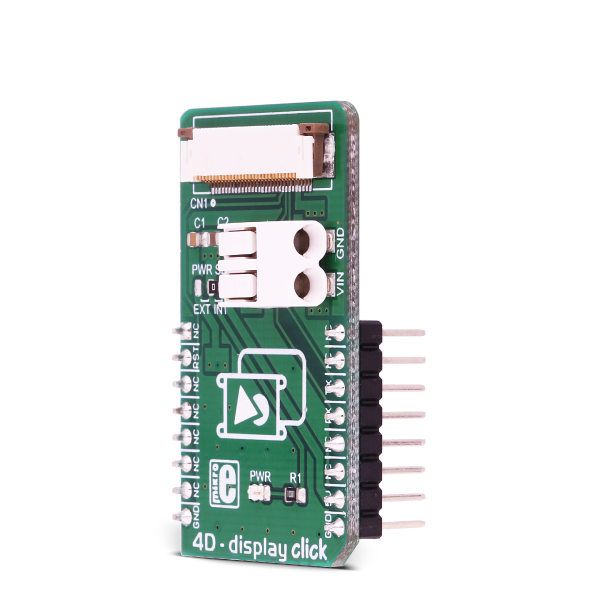
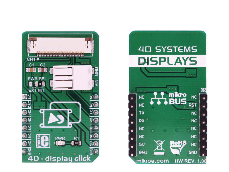
4D - display click is an adapter Click board that offers a mikroBUS interface for controlling 4D Systems gen4 Series intelligent Display Modules. 4D Systems designs and manufactures a wide range of Intelligent Display Modules equipped with powerful graphics processors.

No Abuse Reported

Do you want to subscribe in order to receive notifications regarding "4D - display click" changes.

Do you want to unsubscribe in order to stop receiving notifications regarding "4D - display click" changes.

Do you want to report abuse regarding "4D - display click".

  • Information
  • Comments (0)
DOWNLOAD LINK RELATED COMPILER CONTAINS
mikroBasic PRO for ARM
  • lib
  • src
  • exa
  • hlp
  • hex
  • sch
  • pcb
  • doc
mikroBasic PRO for AVR
  • lib
  • src
  • exa
  • hlp
  • hex
  • sch
  • pcb
  • doc
mikroBasic PRO for dsPIC30/33 & PIC24
  • lib
  • src
  • exa
  • hlp
  • hex
  • sch
  • pcb
  • doc
mikroBasic PRO for FT90x
  • lib
  • src
  • exa
  • hlp
  • hex
  • sch
  • pcb
  • doc
mikroBasic PRO for PIC
  • lib
  • src
  • exa
  • hlp
  • hex
  • sch
  • pcb
  • doc
mikroBasic PRO for PIC32
  • lib
  • src
  • exa
  • hlp
  • hex
  • sch
  • pcb
  • doc
mikroC PRO for ARM
  • lib
  • src
  • exa
  • hlp
  • hex
  • sch
  • pcb
  • doc
mikroC PRO for AVR
  • lib
  • src
  • exa
  • hlp
  • hex
  • sch
  • pcb
  • doc
mikroC PRO for dsPIC30/33 & PIC24
  • lib
  • src
  • exa
  • hlp
  • hex
  • sch
  • pcb
  • doc
mikroC PRO for FT90x
  • lib
  • src
  • exa
  • hlp
  • hex
  • sch
  • pcb
  • doc
mikroC PRO for PIC
  • lib
  • src
  • exa
  • hlp
  • hex
  • sch
  • pcb
  • doc
mikroC PRO for PIC32
  • lib
  • src
  • exa
  • hlp
  • hex
  • sch
  • pcb
  • doc
mikroPascal PRO for ARM
  • lib
  • src
  • exa
  • hlp
  • hex
  • sch
  • pcb
  • doc
mikroPascal PRO for AVR
  • lib
  • src
  • exa
  • hlp
  • hex
  • sch
  • pcb
  • doc
mikroPascal PRO for dsPIC30/33 & PIC24
  • lib
  • src
  • exa
  • hlp
  • hex
  • sch
  • pcb
  • doc
mikroPascal PRO for FT90x
  • lib
  • src
  • exa
  • hlp
  • hex
  • sch
  • pcb
  • doc
mikroPascal PRO for PIC
  • lib
  • src
  • exa
  • hlp
  • hex
  • sch
  • pcb
  • doc
mikroPascal PRO for PIC32
  • lib
  • src
  • exa
  • hlp
  • hex
  • sch
  • pcb
  • doc
Other Compiler
  • lib
  • src
  • exa
  • hlp
  • hex
  • sch
  • pcb
  • doc

mikroSDK Library Blog

4D - display click

4D - display click

Native view of the 4D - display Click board.

View full image
4D - display click

4D - display click

Front and back view of the 4D - display Click board.

View full image

Library Description

Library performs the control of the 4D Systems LCD displays via UART interface by sending the determined commands. The commands can read the objects and write the desired value to the objects, also they support sending the report from the device to the host. Before we start to use this library, first we must perform the LCD display programming. The UART baud rate on LCD and UART baud rate on the host device must be the same. The user can use our demo application for the 4D Systems LCD display, which simulates the speed measurement. For more details check the documentation.

Key functions

  • void c4d_writeObj( T_C4D_OBJ_P obj ) - Function writes the desired value to the desired object.
  • void c4d_readObj( T_C4D_OBJ_P obj ) - Function reads the value of the desired object.
  • uint8_t c4d_sendCommand( uint8_t _command, uint8_t *dataIn, uint8_t nBytes ) - Function sends command to the display.

Example description

The application is composed of three sections:

  • System Initialization - Initializes peripherals and pins.
  • Application Initialization - Initializes UART driver, configures timer and puts all objects on the display to the inactive state (initializes display). Also waits about 5 seconds to stabilize the display.
  • Application Task - (code snippet) - Performs the display control. The application represents speed measurement. First checks isstart button enabled, and when is it true, reads the value of the slider object and represents that value to the other objects. The slider value is controled by the timer. The user should put Start switch to active state (start application) when Ready LED becomes green. Note: Before you start using this code, first you must perform the display programming by using workshop application. The display programming will define all objects and show your desired objects on the display. Also the microSD card is necessary when you start the display programming, and must be formated as FAT16. When programming is finished puts the microSD card on the display device and then you can start to use this example,
    to control all objects on the display.
void applicationTask()
{
 c4d_readObj( (T_C4D_OBJ_P)&dipswitch0 );

 if (dipswitch0.objValue != _C4D_INACTIVE_STATE)
 {
 if (enCheck == _C4D_INACTIVE_STATE)
 {
 led0.objValue = _C4D_ACTIVE_STATE;
 c4d_writeObj( (T_C4D_OBJ_P)&led0 );
 enCheck = _C4D_ACTIVE_STATE;
 TIM2_CR1.CEN = _C4D_ACTIVE_STATE;
 }

 if (slider0.objValue != prevState)
 {
 leddigits0.objValue = slider0.objValue * 10;
 coolgauge0.objValue = slider0.objValue;

 if (slider0.objValue != _C4D_INACTIVE_STATE)
 {
 userled2.objValue = _C4D_ACTIVE_STATE;
 }
 else
 {
 userled2.objValue = _C4D_INACTIVE_STATE;
 }
 if (slider0.objValue >= 100)
 {
 userled1.objValue = _C4D_ACTIVE_STATE;
 }
 else
 {
 userled1.objValue = _C4D_INACTIVE_STATE;
 }
 if (slider0.objValue >= 200)
 {
 userled0.objValue = _C4D_ACTIVE_STATE;
 }
 else
 {
 userled0.objValue = _C4D_INACTIVE_STATE;
 }

 c4d_writeObj( (T_C4D_OBJ_P)&slider0 );
 c4d_writeObj( (T_C4D_OBJ_P)&leddigits0 );
 c4d_writeObj( (T_C4D_OBJ_P)&coolgauge0 );
 c4d_writeObj( (T_C4D_OBJ_P)&userled0 );
 c4d_writeObj( (T_C4D_OBJ_P)&userled1 );
 c4d_writeObj( (T_C4D_OBJ_P)&userled2 );
 prevState = slider0.objValue;
 }
 }
 else if (enCheck == _C4D_ACTIVE_STATE)
 {
 TIM2_CR1.CEN = _C4D_INACTIVE_STATE;
 slider0.objValue = _C4D_INACTIVE_STATE;
 leddigits0.objValue = _C4D_INACTIVE_STATE;
 coolgauge0.objValue = _C4D_INACTIVE_STATE;
 userled0.objValue = _C4D_INACTIVE_STATE;
 userled1.objValue = _C4D_INACTIVE_STATE;
 userled2.objValue = _C4D_INACTIVE_STATE;
 led0.objValue = _C4D_INACTIVE_STATE;
 prevState = slider0.objValue;
 enCheck = _C4D_INACTIVE_STATE;
 transmission1 = _C4D_INACTIVE_STATE;
 transmission2 = _C4D_INACTIVE_STATE;
 transmission3 = _C4D_INACTIVE_STATE;

 c4d_writeObj( (T_C4D_OBJ_P)&slider0 );
 c4d_writeObj( (T_C4D_OBJ_P)&leddigits0 );
 c4d_writeObj( (T_C4D_OBJ_P)&coolgauge0 );
 c4d_writeObj( (T_C4D_OBJ_P)&userled0 );
 c4d_writeObj( (T_C4D_OBJ_P)&userled1 );
 c4d_writeObj( (T_C4D_OBJ_P)&userled2 );
 c4d_writeObj( (T_C4D_OBJ_P)&led0 );
 }
}


Additional Functions :

  • Timer interrupt function is used to control the slider object value and on that way we simulate the speed changing.


Other MikroElektronika libraries used in the example:

  • UART

Additional notes and information

Depending on the development board you are using, you may need USB UART click, USB UART 2 click or RS232 click to connect to your PC, for development systems with no UART to USB interface available on the board. The terminal available in all MikroElektronika compilers, or any other terminal application of your choice, can be used to read the message.

ALSO FROM THIS AUTHOR

Proximity 15 click

0

Proximity 15 Click is a compact add-on board that contains a close-range proximity sensing solution. This board features the VL53L1, a state-of-the-art, Time-of-Flight (ToF), a laser-ranging miniature sensor from STMicroelectronics.

[Learn More]

6DOF IMU 13 Click

5

6DOF IMU 13 Click is a compact add-on board that contains an eCompass that consists of a 3-axis linear accelerometer and a 3-axis magnetic field sensor. This board features the MC6470, a 6 DoF accelerometer, and a magnetometer sensor solution, from mCube Inc.

[Learn More]

R Meter click

0

R Meter click is a mikroBUS add-on board with circuitry for measuring the value of resistors.

[Learn More]