TOP Contributors

  1. MIKROE (2656 codes)
  2. Alcides Ramos (353 codes)
  3. Shawon Shahryiar (307 codes)
  4. jm_palomino (112 codes)
  5. Chisanga Mumba (90 codes)
  6. S P (73 codes)
  7. dany (71 codes)
  8. MikroBUS.NET Team (35 codes)
  9. NART SCHINACKOW (34 codes)
  10. Armstrong Subero (27 codes)

Most Downloaded

  1. Timer Calculator (136884 times)
  2. FAT32 Library (70004 times)
  3. Network Ethernet Library (56001 times)
  4. USB Device Library (46305 times)
  5. Network WiFi Library (41932 times)
  6. FT800 Library (41208 times)
  7. GSM click (29014 times)
  8. PID Library (26423 times)
  9. mikroSDK (26398 times)
  10. microSD click (25386 times)
Libstock prefers package manager

Package Manager

We strongly encourage users to use Package manager for sharing their code on Libstock website, because it boosts your efficiency and leaves the end user with no room for error. [more info]

< Back
mikroSDK Library

DC Motor 3 click

Rating:

1

Author: MIKROE

Last Updated: 2019-03-08

Package Version: 1.0.0.1

mikroSDK Library: 1.0.0.0

Category: Brushed

Downloaded: 4436 times

Not followed.

License: MIT license  

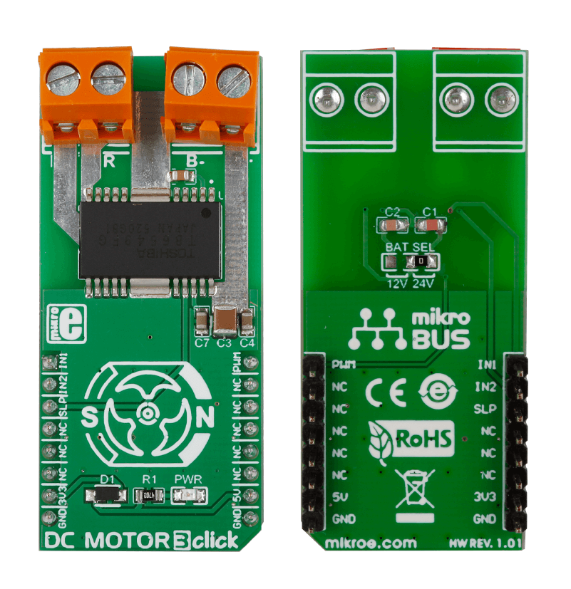
DC Motor 3 click is a mikroBUS add-on board with a Toshiba TB6549FG full-bridge driver for direct current motors. The IC is capable of outputting currents of up to 3.5 A with 30V, making it suitable for high-power motors.

The click communicates with the target MCU through the mikroBUS PWM pin.
Designed to use a 3.3 power supply only.

No Abuse Reported

Do you want to subscribe in order to receive notifications regarding "DC Motor 3 click" changes.

Do you want to unsubscribe in order to stop receiving notifications regarding "DC Motor 3 click" changes.

Do you want to report abuse regarding "DC Motor 3 click".

  • mikroSDK Library 2.0.0.0
  • Comments (0)
DOWNLOAD LINK RELATED COMPILER CONTAINS
mikroBasic PRO for ARM
  • lib
  • src
  • exa
  • hlp
  • hex
  • sch
  • pcb
  • doc
mikroBasic PRO for AVR
  • lib
  • src
  • exa
  • hlp
  • hex
  • sch
  • pcb
  • doc
mikroBasic PRO for dsPIC30/33 & PIC24
  • lib
  • src
  • exa
  • hlp
  • hex
  • sch
  • pcb
  • doc
mikroBasic PRO for FT90x
  • lib
  • src
  • exa
  • hlp
  • hex
  • sch
  • pcb
  • doc
mikroBasic PRO for PIC
  • lib
  • src
  • exa
  • hlp
  • hex
  • sch
  • pcb
  • doc
mikroBasic PRO for PIC32
  • lib
  • src
  • exa
  • hlp
  • hex
  • sch
  • pcb
  • doc
mikroC PRO for ARM
  • lib
  • src
  • exa
  • hlp
  • hex
  • sch
  • pcb
  • doc
mikroC PRO for AVR
  • lib
  • src
  • exa
  • hlp
  • hex
  • sch
  • pcb
  • doc
mikroC PRO for dsPIC30/33 & PIC24
  • lib
  • src
  • exa
  • hlp
  • hex
  • sch
  • pcb
  • doc
mikroC PRO for FT90x
  • lib
  • src
  • exa
  • hlp
  • hex
  • sch
  • pcb
  • doc
mikroC PRO for PIC
  • lib
  • src
  • exa
  • hlp
  • hex
  • sch
  • pcb
  • doc
mikroC PRO for PIC32
  • lib
  • src
  • exa
  • hlp
  • hex
  • sch
  • pcb
  • doc
mikroPascal PRO for ARM
  • lib
  • src
  • exa
  • hlp
  • hex
  • sch
  • pcb
  • doc
mikroPascal PRO for AVR
  • lib
  • src
  • exa
  • hlp
  • hex
  • sch
  • pcb
  • doc
mikroPascal PRO for dsPIC30/33 & PIC24
  • lib
  • src
  • exa
  • hlp
  • hex
  • sch
  • pcb
  • doc
mikroPascal PRO for FT90x
  • lib
  • src
  • exa
  • hlp
  • hex
  • sch
  • pcb
  • doc
mikroPascal PRO for PIC
  • lib
  • src
  • exa
  • hlp
  • hex
  • sch
  • pcb
  • doc
mikroPascal PRO for PIC32
  • lib
  • src
  • exa
  • hlp
  • hex
  • sch
  • pcb
  • doc

mikroSDK Library Blog

DC Motor 3 click

DC Motor 3 click

Font and back view of the DC Motor 3 click board

View full image

Library Description

The library covers all the necessary functions to control DC Motor 3 Click board. DC Motor 3 Click communicates with the target board via the PWM module. This library contains drivers to enable or disable the engine, for rotation in the clockwise or counterclockwise direction, for the break and stop the motor and for PWM function: initialization, for sets duty ratio, starts and stops PWM module.

Key functions:

  • void dcmotor3_enable() - Enable the motor function.
  • void dcmotor3_counterClockwise()- Set the direction of rotation in the counter clockwise direction function.
  • void dcmotor3_clockwise() - Set the direction of rotation in the clockwise direction function.

Examples description

The application is composed of three sections:

  • System Initialization - Initializes GPIO and LOG structures, sets AN, RST, CS, and PWM pins as output.
  • Application Initialization -  Initialization driver enables - GPIO, PWM initialization set PWM duty cycle and PWM frequency, start PWM, enable the engine, and start to write log.
  • Application Task - (code snippet) This is an example which demonstrates the use of DC Motor 3 Click board. DC Motor 3 Click communicates with register via PWM interface.
    Its shows moving in the clockwise direction of rotation from slow to fast speed and moving in the counterclockwise direction of rotation from fast to slow speed.
    Results are being sent to the Usart Terminal where you can track their changes.
void applicationTask() 
{
    mikrobus_logWrite( "   Brake the engine  ", _LOG_LINE );
    dcmotor3_shortBrake();
    Delay_1sec();
    
    mikrobus_logWrite( "---------------------", _LOG_LINE );
    mikrobus_logWrite( "      Clockwise      ", _LOG_LINE );
    dcmotor3_clockwise();
    Delay_1sec();
 
    for ( dutyCycle = 500; dutyCycle < 3000; dutyCycle += 250 )
    {
        dcmotor3_pwmSetDuty( dutyCycle );
        mikrobus_logWrite( " >", _LOG_TEXT );
        Delay_1sec();
    }
 
    mikrobus_logWrite( "", _LOG_LINE );
    mikrobus_logWrite( "---------------------", _LOG_LINE );
    mikrobus_logWrite( "   Brake the engine  ", _LOG_LINE );
    dcmotor3_shortBrake();
    Delay_1sec();

    mikrobus_logWrite( "---------------------", _LOG_LINE );  
    mikrobus_logWrite( "  Counter Clockwise  ", _LOG_LINE );
    dcmotor3_counterClockwise();
    Delay_1sec();
 
    for ( dutyCycle = 3000; dutyCycle > 500; dutyCycle -= 250 )
    {
        dcmotor3_pwmSetDuty( dutyCycle );
        mikrobus_logWrite( " <", _LOG_TEXT );
        Delay_1sec();
    }
  
    mikrobus_logWrite( "", _LOG_LINE );
    mikrobus_logWrite( "---------------------", _LOG_LINE );
    Delay_1sec();
}  

Additional Functions :

  • uint32_t dcmotor3_pwmInit( uint16_t freq ) - Initializes the Timer module in PWM mode.
  • void dcmotor3_pwmSetDuty( uint16_t duty ) - The function changes PWM duty ratio.
  • void dcmotor3_pwmStart() Starts appropriate PWM module.
  • void dcmotor3_pwmStop() - Stops appropriate PWM module.

Other mikroE Libraries used in the example:

  • PWM
  • UART

Additional notes and informations

Depending on the development board you are using, you may need USB UART clickUSB UART 2 click or RS232 click to connect to your PC, for development systems with no UART to USB interface available on the board. The terminal available in all MikroElektronika compilers, or any other terminal application of your choice, can be used to read the message

ALSO FROM THIS AUTHOR

6DOF IMU 4 click

5

6DOF IMU 4 Click is an advanced 6-axis motion tracking Click board, which utilizes the ICM-20602, a high-performance integrated motion sensor, equipped with a 3-axis gyroscope, and a 3-axis accelerometer.

[Learn More]

Line Follower click

0

Line Follower Click carries an array of five QRE1113 miniature reflective object sensors. As the name implies, Line Follower click is best used for line following robots and cars.

[Learn More]

LED Driver 12 click

0

LED Driver 12 Click is a compact add-on board that simplifies the control of multiple LEDs. This board features the PCA9532, a 16-bit I2C-configurable I/O expander optimized for dimming LEDs in 256 discrete Red/Green/Blue (RGB) steps from NXP Semiconductors. The PCA9532 offers high efficiency, supporting up to 16 LED channels and delivering a maximum of up to 25mA of LED current per channel. It contains an internal oscillator with two user-programmable blink rates and duty cycles coupled to the output PWM. Any bits not used for controlling the LEDs can be used for GPIO expansion, which provides a simple solution when additional I/O is needed for some sensors, push-buttons, or alarm monitoring. This Click board™ is suitable for color mixing and backlight application for amusement products, LED status signalization, home automation projects, and many more.

[Learn More]