We strongly encourage users to use Package manager for sharing their code on Libstock website, because it boosts your efficiency and leaves the end user with no room for error. [more info]

Rating:
Author: MIKROE
Last Updated: 2015-04-17
Package Version: 1.0.0.0
Example: 1.0.0.0
Category: Communication
Downloaded: 1621 times
Not followed.
License: MIT license
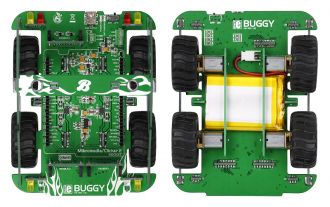
This example demonstrates wireless Buggy control, using clicker2 for STM32/PIC32/PIC18FJ/FT900, BLE-P click board and Android smart phone.
Do you want to subscribe in order to receive notifications regarding "Buggy example" changes.
Do you want to unsubscribe in order to stop receiving notifications regarding "Buggy example" changes.
Do you want to report abuse regarding "Buggy example".
| DOWNLOAD LINK | RELATED COMPILER | CONTAINS |
|---|---|---|
| 1422546857_buggy_example_mikroc_arm.zip [79.80KB] | mikroC PRO for ARM |
|
| 1426863818_buggy_example_mikroc_pic.zip [76.89KB] | mikroC PRO for PIC |
|
| 1426863842_buggy_example_mikroc_pic32.zip [77.62KB] | mikroC PRO for PIC32 |
|
| 1429258342_buggy_example_mikroc_ft90x.zip [82.35KB] | mikroC PRO for FT90x |
|

If you want to take your Buggy for a spin as soon as possible, attach BLE P click to one of the three mikroBUS sockets, and install the free Buggy Android app on your nearest Bluetooth Low Energy compatible smartphone or tablet. The source code is available for free. Use it to tailor the app for any number of specific uses you intended for the Buggy. Examples are written for :
- Clicker 2 Board for STM32 - STM32F407VG
- Clicker 2 Board for PIC18FJ - PIC18F87J50
- Clicker 2 Board for PIC32MX - PIC32MX460F512L
- Clicker 2 Board for FT900 - FT900
