20%

We strongly encourage users to use Package manager for sharing their code on Libstock website, because it boosts your efficiency and leaves the end user with no room for error. [more info]

Rating:
Author: dany
Last Updated: 2019-10-23
Package Version: 2.0.0.0
Category: Other Codes
Downloaded: 1234 times
Followed by: 1 user
License: MIT license
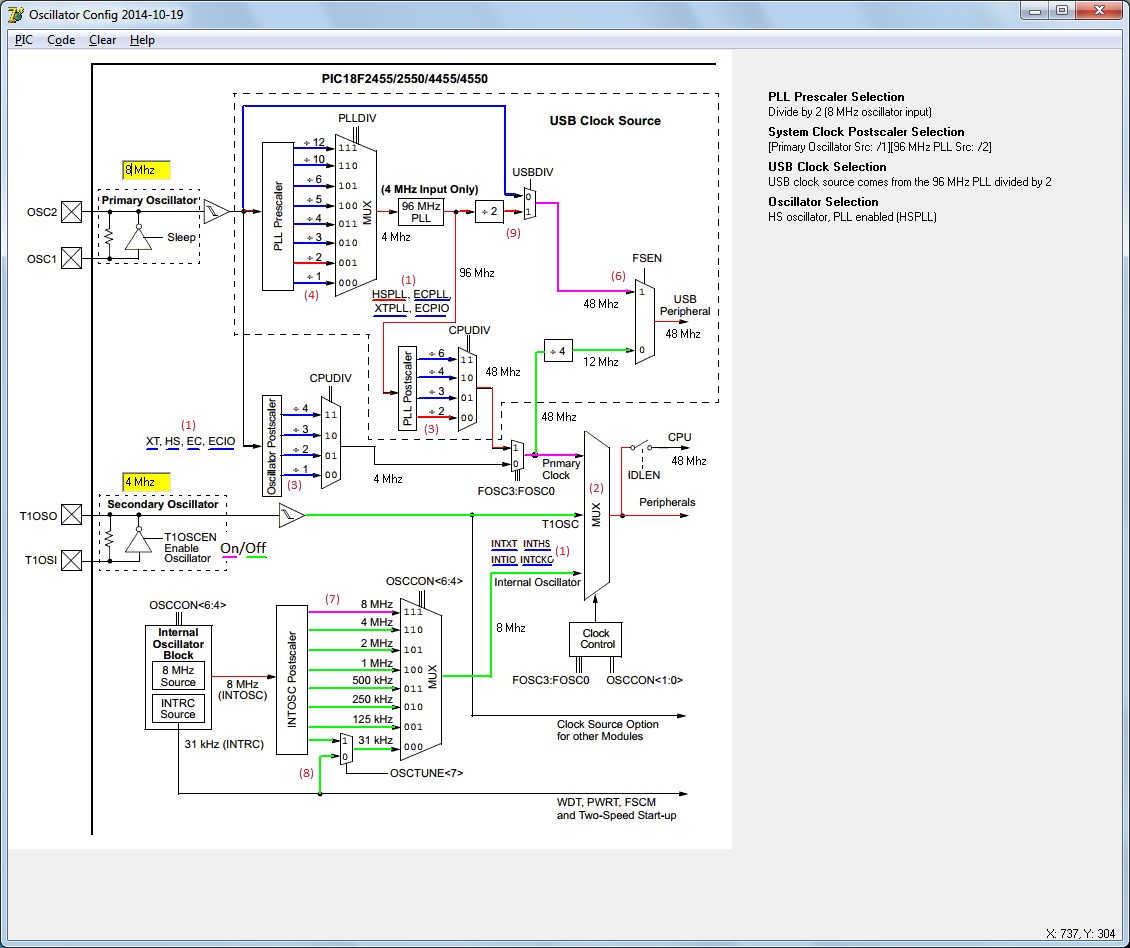
This tool helps, starting from the PIC18 or PIC24 oscillator block diagram, to define the oscillator related configuration settings and initialisation code. Only a limited number of PIC's is supported so far.
Do you want to subscribe in order to receive notifications regarding "Tool: PIC Oscillator configuration and initialisation code generator" changes.
Do you want to unsubscribe in order to stop receiving notifications regarding "Tool: PIC Oscillator configuration and initialisation code generator" changes.
Do you want to report abuse regarding "Tool: PIC Oscillator configuration and initialisation code generator".
| DOWNLOAD LINK | RELATED COMPILER | CONTAINS |
|---|---|---|
| 1571856771_tool__pic_oscill_mikropascal_other.zip [3.98MB] |
|
|
| 1522252906_tool__pic_oscill_other_pic.zip [62.85KB] | Other PIC Compilers |
|

The green lines are the selectable paths or oscillator types that are defined in the config bits, the red lines are those that are selected. The green lines are the paths or settings that are selectable by register settings (init code), the fuhsia lines
View full imageThere are a lot of problems in PIC projects due to wrong oscillator settings and or the wrong initialisation code.. It is not easy to make the right selections in the "Project Settings" screen, even when looking to the oscillator block diagram. The names of the items do not match.
To make it (more) easy, this tool is developed, I got the idea from here: http://www.mikroe.com/forum/viewtopic.php?f=3&t=57236&start=7 Thanks VCC!.
Its output are the values to be chosen in the Project settings and (if appropriate) the necessary oscillator initialisation code.
The input of the tool is the following:
- the (modified) oscillator block diagram (from datasheet), one per PIC family
- a text file with the description of what the lines (clock paths or parts of them) mean, (one for each PIC family), one per PIC family
- the content of the .mlk file of the processor concerned, delivered with the compiler
- the user selection in the tool, on the (modified) block diagram, of oscillator types and the clock paths he/she wants to use (this is what the user has to do to actually use the tool). At this moment following PIC's are supported: P18F2455,P18F2550,P18F4455,P18F4550
P18F2525,P18F2620,P18F4525,P18F4620
P18F24J50,P18F25J50,P18F26J50,P18F44J50,P18F46J50
P18F26J53,P18F27J53,P18F46J53,P18F47J53
P18F23K22,P18F24K22,P18F25K22,P18F26K22,P18F43K22,P18F44K22,P18F45K22,P18F46K2 P18F66J60, P18F66J65, P18F67J60, P18F86J60, P18F86J65, P18F87J60, P18F96J60, P18F96J65, P18F97J60
P24FJ16GA002,P24FJ32GA002,P24FJ48GA002,P24FJ64GA002,P24FJ16GA004
P24FJ32GA004,P24FJ48GA004,P24FJ64GA004
P24FJ32GB002,P24FJ64GB002,P24FJ32GB004,P24FJ64GB004 It is a lot of work to prepare the necessary files for a certain PIC family, so it would be nice if user's of a certain PIC family would/could generate those files. Currently this has to be done manually. The necessary files are the textfile and the modified oscillator blockdiagram. Have fun! To be complete: here is the Delphi (Delphi 7) source of the tool: https://libstock.mikroe.com/projects/download/1125/9026/1522252906_tool__pic_oscill_other_pic.zip
Installation of the tool: copy all files in "Oscillator_Configuration.zip" to a dedicated directory. Start up the tool by clicking "Oscillator_Configuration.exe".
Version 2.0 (2014-10-19): Added the possibility to show frequencies (entered or calculated) in the oscillator diagram. The formulas for the frequency outputs have only been added in the textfile for the P18F2550 and the P18F2620 families. Soon the others will be extended.
2014-10-20: An original configuration is shown now, based on the order of settings in the pic's .txt file, after selection of a PIC.
2014-10-24: All frequency values are added now, except for the P24F64GB002 family.
2014-10-25: Frequency calculations also added for the P24F64GB002 family.
2014-11-03: Updated the manual. Some parts are still to be filled.
2014-11-11: the manual has been completed.
2014-11-26: the following PIC's are supported now: P18F66J60, P18F66J65, P18F67J60, P18F86J60, P18F86J65, P18F87J60, P18F96J60, P18F96J65, P18F97J60
2014-11-30: corrected a few small errors.
2019-10-23: removed an error in the P18F47J53 formula definition.


